DC Fan Project
Purpose
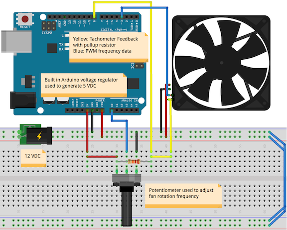
The purpose of this project is to use the Atmel 328p microcontroller to control the speed of a 12V DC fan. The microcontroller is to take input from a potentiometer and vary the rotation frequency accordingly.
Part A. Getting Acquainted with the fan
- What is the typical operating voltage and current draw of this fan?
12 VDC, 0.34 A - Identify the name, colour and function of each of the four wires.
Black: GND
Red: Vcc
Yellow: Pulse
Blue: PWM - What is the operating voltage range of the PWM signal?
2.8 V-6 V - What is the recommended frequency range of the fan's PWM signal?
22 kHz-28 kHz - What operating conditions produce a detectable audio hum emanating from the fan and how can it be eliminated?
If PWM frequency is in the range of 20 Hz-20 kHz, it will produce an audible hum. To fix this, increase PWM frequency until it is out of range of human hearing (ideally above 20 kHz) - What is the frequency of the Arduino's PWM signal from it's analogWrite() function? Explain why.
The Arduino PWM frequency is 980Hz or 490Hz. This is because the prescaler is set on the timers connected to the PWM pins. - Can the Arduino handle the Fan's PWM requirements 'easily'? If not, what course of action must be considered?
No, as the Arduino PWM frequency is much less than 22kHz. A timer interrupt must be used to produce a PWM signal. - What is meant be the term open collector (aka open drain)? To which wire colour does this pertain and what additional component is required to facilitate the correct performance of this function?
This means that the output pin is the collector pin of a grounded NPN transistor. This means that the pin is either in a ground or floating state. This pertains to the yellow wire. To use this pin a pull up resistor is required. - What is the FREQUENCY:ROTATION ratio of the output sense wire?
2:1
Part B. Hardware Design
Part C. PWM Design
This project uses the PWM (pulse-width modulation) functions of the 328p to adjust the fan rotation frequency. The fan interprets the duty cycle of the PWM signal. As such, the frequency of the PWM signal must be constant and the duty cycle should change according to the position of the potentiometer. Using mode 7 in conjunction with the OCR2A and OCR2B registers, the duty cycle and frequency can be independently adjusted. The formula to convert frequency (in Hz) to a value which OCR2A can understand is:
This value can range from 0-255 and it determines the value at which the counter attached to timer 2 should reset to zero. Here we have defined it as 80 with a prescaler of 8 for a PWM frequency of 25 kHz. To augment the duty cycle of the PWM signal, the microcontroller uses the value of OCR2B. The larger the value stored in OCR2B, the greater the duty cycle. Each time the counter resets (according to the value of OCR2A), the pin state changes to HIGH until the value reaches that of OCR2B and it changes to LOW.
Part D. Fan Speed (ADC)
The DC Fan code uses the analog to digital converter (ADC) built into the 328p to determine the speed at which the user wants the fan to operate. The external circuit is a voltage divider from 5V-0V. The microcontroller interprets this voltage as a 10-bit value which is then converted to a duty cycle value and stored in OCR2B.Timer 0 controls the ADC by sending out a request for data each time it overflows. The prescaler value of timer 0 determines the frequency of this request. An empty interrupt must be set in order to properly trigger the ADC read. In this example it is set to request ADC data 64 times per second. When the ADC has data to return, another interrupt occurs. Only the upper byte of this data is used (as the duty cycle can only be an 8-bit value) so the ADLAR value is set. This is then mapped to a duty cycle value and the duty cycle changes during the next interrupt of the PWM timer. The code discards the first value of the ADC, in accordance to Atmel guidelines, as the first read is often inaccurate.
Part E. Sense (Feedback, Tachometry, Yellow Wire)
The purpose of the sense system is to determine whether or not the fan is operating as desired. By combining this data with the abilities of PID, the user can have more precise control over the fan speed. The yellow wire changes state four times per revolution of the fan. This wire requires a pullup resistor as it is an open gate pin. Without this resistor, the pin would either be in a ground or floating state. By pulling the wire up to +5V, the microcontroller can determine how often the state changes. The 328p records the speed of the fan by use of an external interrupt. Each time the pin is in a HIGH state the interrupt triggers and increases the pulseCount register by one. The ICES1 bit in TCCRB1 is set to ensure that the program operates in this way. Each second, as determined by the overflow of timer 1, the program compares the value of this register to the theoretical rotation/second value defined in the datasheet. The program uses the ADC defined duty cycle to index an array and determine what the rotation/second value should be. In this array the rotation/second values are twice the actual values because the external interrupt triggers twice per revolution.
Part F. Serial Communication (USART: Universal Synchronous/Asynchronous serial Receive and Transmit)
By using USART the microcontroller can relay to the user the current state of the program. In this project the microcontroller tells the computer how closely the fan is rotating to the intended value. The 328p first configures USART to send data in the UARTInit label. The baud rate set here is a function of the F_CPU value. To get 9600 baud at 16 MHz the value stored in UBRR0 (a two-byte word) must be 103. To send data out the TXEN0 bit in the UCSROB register must be set high. If the microcontroller needed to receive data, the RXEN0 bit in this register would be set. Note that each call of the USART registers includes a ‘0’ because there can be multiple USART communication interfaces on the same chip. Each time timer 1 overflows, the difference between the ideal value and the actual value of the rotations/second is sent over USART. Added to this value is an ASCII ‘A’ or sixty-five as the graphing utility cannot understand negative numbers (and the rpm in some cases may be less than expected). This provides a buffer between the difference and zero.
Part G. Graphic Visualization
By using Data visualizer tool included with Atmel Studio 7 one can interpret the data sent over USART to the computer. The 328p Arduino connects to the computer via a USB cable. Selecting the proper COM port and baud rate in the visualizer will return rotation/second values that the graph function can display.
Part H. PID (Proportional – Integral – Derivative)
PID completes the link between the feedback and PWM signals of the DC fan. Often the desired and actual values of the rotation/second of the fan are not the same. PID remedies this by proportionally scaling up or down the duty cycle as the rotation/second approaches the desired level. This alone will never reach the desired value, so PID uses the integral between the actual rotation/second and the desired level to complete the operation. Using the derivative of the actual rotation/second function helps the program understand how much to adjust the duty cycle in order to have the desired effect.
Media
 | 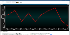 |
| Completed Fan Circuit | Graphic Visualizer screenshot |
|---|---|
 | 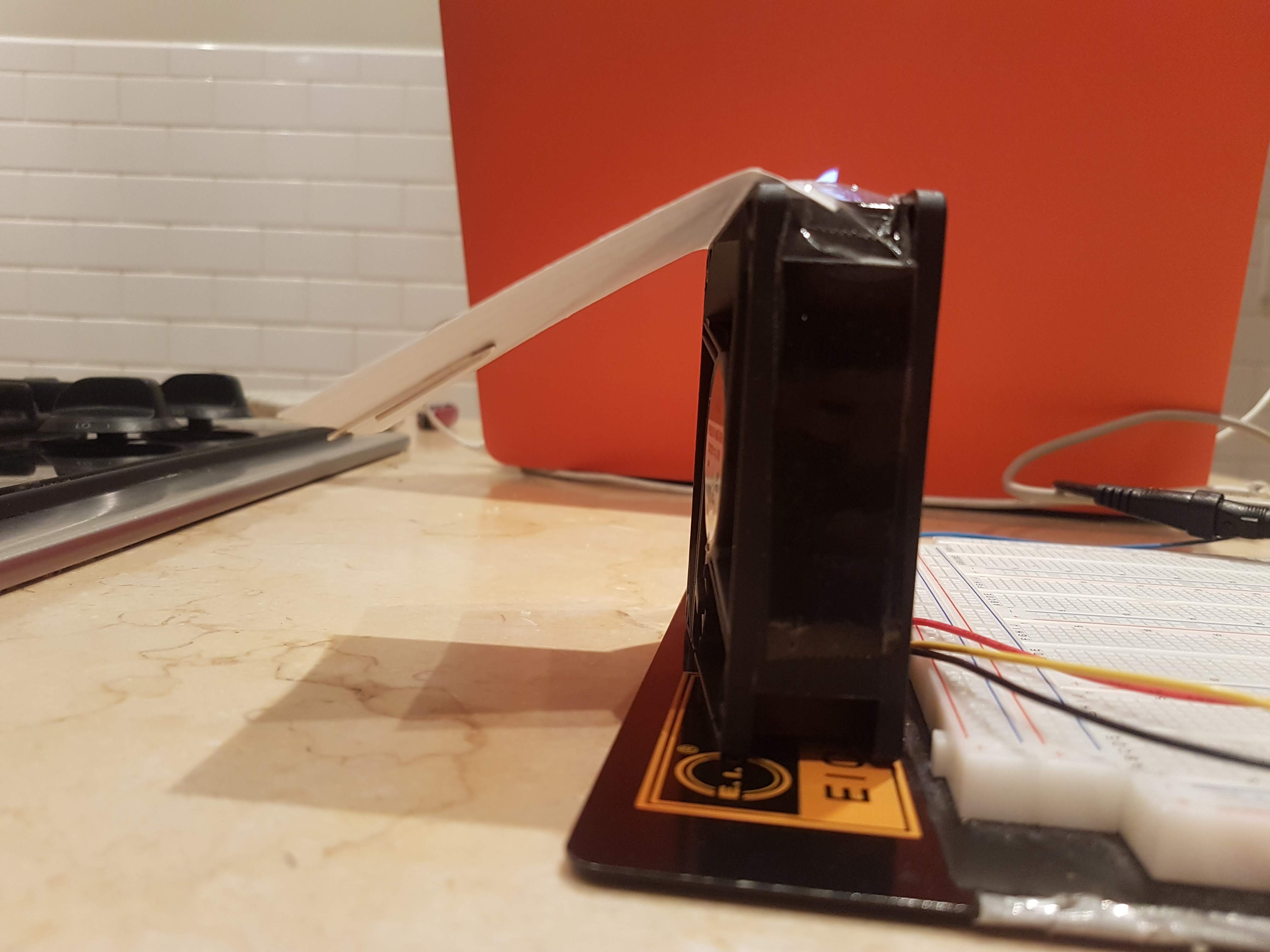 |
| Close up of tach wire & pot | Fan at full speed blowing paper card |
| Link to YouTube Video: https://youtu.be/PMThd7WUhio | |
Code
; DCfan.asm
;
; Created: 2018-04-11 1:39:45 PM
; Author : Ethan McAuliffe
;
#include "prescalers.h"

#define F_CPU 16000000; cpu freq 16 Mhz
#define PRESCALE 8
#define F_FAN 25000
#define FREQ F_CPU/PRESCALE/F_FAN; (OCR2A) = 80
#define DUTY 40; start with a 40% duty cycle
#define BAUDRATE 103;9600 baud
#define newLine 13;
#define offset 'A';

.def duty         =r19  ;
.def pulseCount   =r20  ;
.def rps          =r21  ;
.def txByte       =r22  ;
.def empirical    =r23  ;
.def setPoint     =r24  ;
.def difference   =r25  ;

.org 0x0000
    rjmp reset
.org 0x0014
    rjmp TIM1_CAPT
.org 0x001A
    rjmp TIM1_OVF
.org 0x0020
    rjmp TIM0_OVF
.org 0x002A
    rjmp ADC_Complete

.org 0x0050

RPMStart:
;.db    900,900,900,900,1200,2000,2700,3400,4050,4500,4800,0
.db 30,30,30,30,40,66,90,113,135,150,160,0 ;rotations/second according to duty cycle from datasheet
RPMEnd:

Greeting:
.db "Hello world! ",newLine //newLine terminated

.org 0x0100;
reset:
    cli              ;
    rcall RPMInit    ;
    rcall PWMInit    ;
    rcall ADCInit    ;
    rcall TM0Init    ;for adc
    rcall TM1Init    ;for input capture
    rcall UARTInit   ;
;   rcall display    ;prints greeting to terminal
;   rcall PIDInit    ;
sei

wait:
    rjmp wait


UARTInit:
    ldi  r16,BAUDRATE>>8
    sts  UBRR0H,r16
    ldi  r16,BAUDRATE
    sts  UBRR0L,r16
    ldi  r16,(1<<TXEN0)     ;RXEN0 for receive
    sts  UCSR0B,r16
    ldi  r16,(1<<UCSZ01) | (1<<UCSZ00)
    sts  UCSR0C,r16
ret

display:
    ldi  xl,low(Greeting<<1)
    ldi  xh,high(Greeting<<1)
    movw z,x
    nextChar:
        lpm   txByte,z+
        rcall transmit
        cpi   txByte,newLine
        brne  nextChar
    ret
transmit:
    lds  r16,UCSR0A         ;read control status register 'A'
    sbrs r16,UDRE0
    rjmp transmit
    sts  UDR0,txByte
ret
ADCInit:
    ser  r16
    sts  DIDR0,r16  ;disable pins to reduce power consumption
    ldi  r16,(1<<REFS0)|(1<<ADLAR)  ;
    sts  ADMUX,r16                  ;
    ;Enable, start dummy conversion, enable timer as trigger, , prescaler...
    ldi  r16,(1<<ADEN)|(1<<ADSC)|(1<<ADATE)|(1<<ADIE)|(1<<ADPS2)|(1<<ADPS1)|(1<<ADPS0);
    sts  ADCSRA,r16                 ;
    ldi  r16,(1<<ADTS2)         ;
    sts  ADCSRB,r16                 ;
dummy:
    ;first read is not accurate - start conversion, check for data, throw away
    lds  r16,ADCSRA ;load ADCSRA register to check dummy flag
    andi r16,1<<ADIF
    breq dummy
ret

RPMInit:
    ldi  xl,low(RPMStart << 1)  ;actually rotations/second as they are smaller and fit in a single byte
    ldi  xh,low(RPMStart << 1)
    ldi  yl,low(RPMEnd << 1)
    ldi  yh,low(RPMEnd << 1)
    movw z,x
ret
PWMInit:
    ldi  r16,(1 << PORTD3)
    out  DDRD,r16
    ldi  r16,(1 << COM2B1) | (1 << WGM21) | (1 << WGM20) ; OC2A disconnected, OC2B connected, MODE 7 (OCR2A as TOP)
    sts  TCCR2A,r16
    ldi  r16,(1 << WGM22) | (1 << T2ps8) ; complete WGM definition and prescaler
    sts  TCCR2B,r16
    ldi  r16,FREQ
    sts  OCR2A,r16
    ldi  r16,DUTY
    sts  OCR2B,r16
ret

TM1Init:
;   clr   r16       ;alternatives to clear a register
;   ldi   r16,0
;   andi  r16,0

    eor  r16,r16
    sts  TCCR1A,r16
    ldi  r16,(T1ps256)|(1<<ICES1) ;input capture rising edge, prescale 256 (2^24)/(2^16)/(2^8)=1/s
    sts  TCCR1B,r16
    ldi  r16,(1<<ICIE1)|(1<<TOIE1);enable input capture and enable timer interrupt overflow enable
    sts  TIMSK1,r16
    clr  pulseCount
ret

TM0Init:
    clr  r16                ;this timer is responsible for telling the ADC to read the value of the potentiometer
    out  TCCR0A,r16     ;
    ldi  r16,T0ps1024   ;2^24/2^10/2^8 = 2^6 = 64 ADC/sec
    out  TCCR0B,r16     ;
    ldi  r16,(1<<TOIE0)
    sts  TIMSK0,r16     ;
ret

TIM0_OVF:
reti                    ;required to have the ADIF cleared

ADC_Complete:
    lds  duty,ADCH      ;load upper byte of adc value
    ldi  r16,FREQ       ;set to 80
    mul  r16,duty       ;multiply by duty
    sts  OCR2B,r1       ;r1 stores high byte of product (divide by 256)
reti

TIM1_CAPT:
    inc  pulseCount
reti

TIM1_OVF:
;   mov  rps,pulseCount ;get number of rotations/second (*2)
;   clr  pulseCount     ;clear immediately to record every pulse
;   lsr  rps
    mov  empirical,pulseCount;[30-160] rps
    clr  pulseCount         ;
    ldi  difference,offset  ;
    add  difference,empirical;
    mov  r16,duty           ;get duty value of [0-80]
    lsr  r16
    lsr  r16                    ;shift right thrice
    lsr  r16
    movw z,x                ;zero index of RPS
    add  zl,r16             ;set index
    lpm  setPoint,z         ;
    sub  difference,setPoint
    mov  txByte,difference  ;place difference in the transmit register
    rcall  transmit         ;transmit the difference
reti
Reference
D'Arcy, Chris. “AVR Assembly Tasks.” ACES, RSGC, 28 Mar. 2018, http://darcy.rsgc.on.ca/ACES/TEI4M/1718/AssemblyTasks.html.