Medium ISP: Photophone
Purpose
The purpose of this project is to convert audio input into light and then back into sound again. The project is to take input from either a 3.5mm headphone jack or a small microphone. It should be simple to change the input source of the device. The receiver circuit should not have any connection to the broadcaster circuit and the lights should be the only way to transmit information between the two. The final product should be able to transmit sound over a reasonable distance (~5m) after reducing external sources of noise or interference.
| Parts List | |
|---|---|
| 4× TDA7052A 1W Mono Audio Amplifier IC | 10kΩ Linear Potentiometer |
| 3.5mm Headphone Jack Breakout Board | 100nF Ceramic Capacitor |
| 100µF Electrolytic Capacitor | 2.2µF Electrolytic Capacitor |
| 1kΩ Resistor | Electret Microphone Amplifier - MAX9814 |
| DC Power Jack | 24W (7.5V@3.2A) DC Power Supply |
| 7805 5V Voltage Regulator | 100mm × 80mm 1W Solar Panel |
| 15W Audio Amplifier Circuit | 8Ω 1W Speaker |
| 32× Super Bright White LEDs |
Procedure
This project begins with researching the operation of the final product. Inspiration for the project came from an episode of MacGyver and, although informative, the photophone represented in the show would not be functional. As such, determining the parts required and general design of the project required more in-depth research.
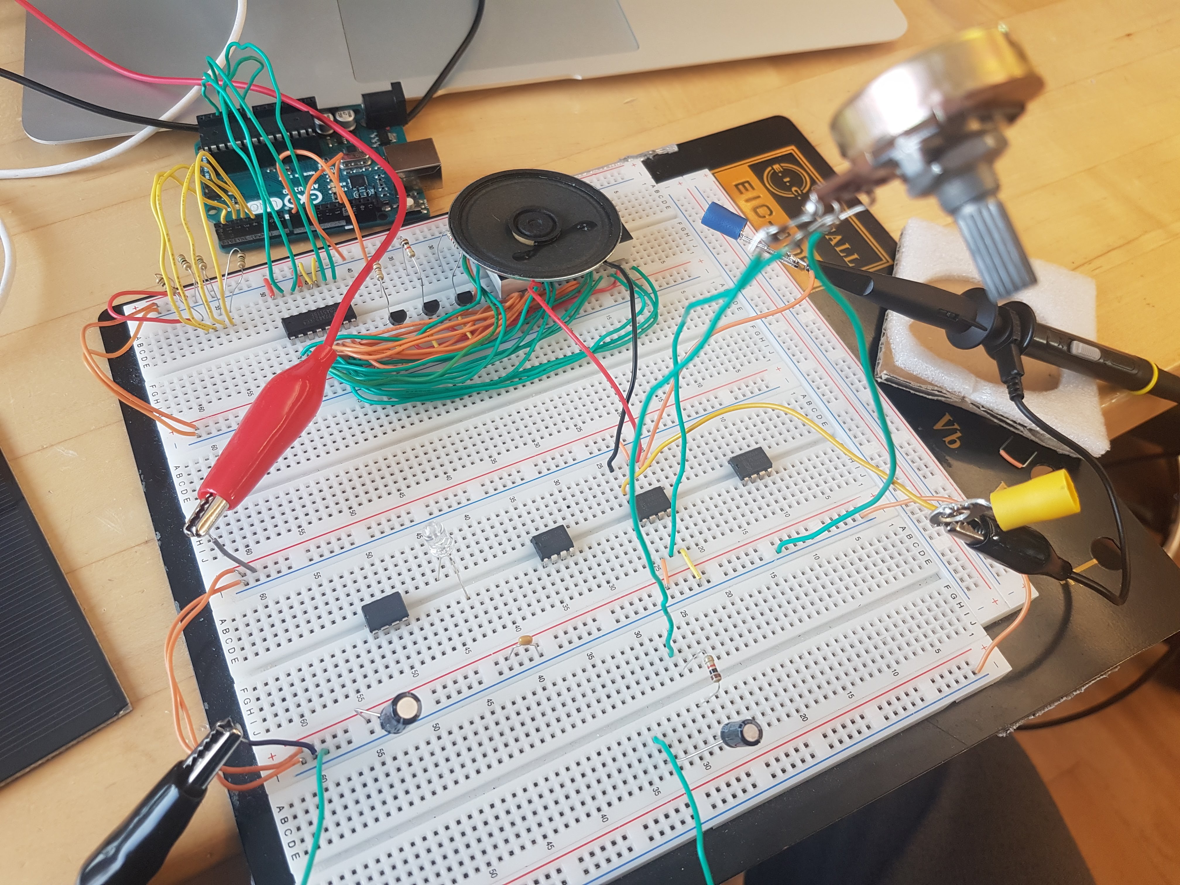
Prototyping a basic audio amplifier circuit was the initial step after researching parts. The first iteration used a general-purpose op-amp IC instead of a higher-resolution IC intended for audio use. This, however, provided a valuable lesson on configuring op-amps for audio circuits. Prototyping this circuit and modifying it to reduce noise and increase quality meant that the next version performed much better. By replacing the IC with an audio focused amplifier, and modifying the circuit accordingly the quality of the audio coming out of the speaker increased even more. At this point the only part restricting audio quality greatly was the speaker.
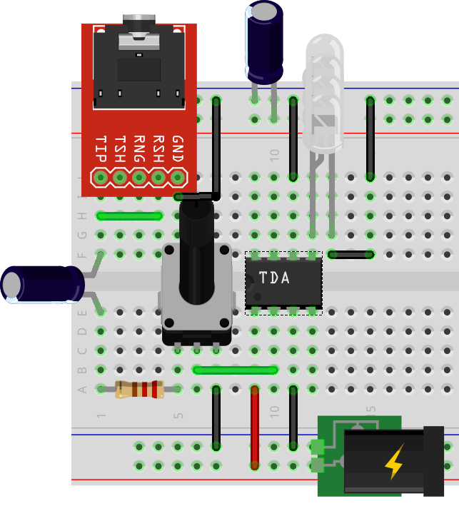
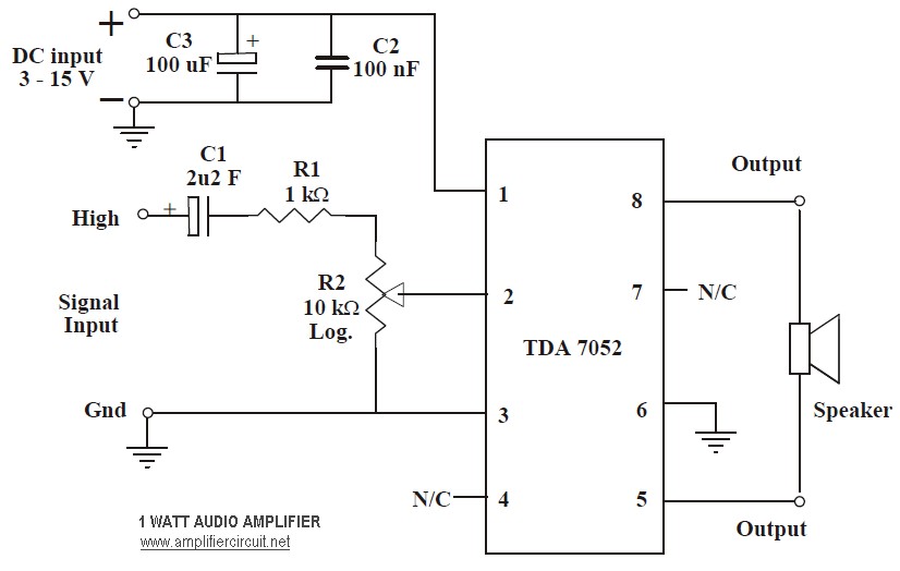
The audio amplifier circuit is special in that it has a built-in high-pass filter. These filters work by restricting the amplitude of frequencies below a certain value. The formula to determine the value at which the amplitude of a specific frequency greatly decreases is , where is resistance in ohms and is capacitance in farads. The high-pass filter in this circuit consists of a 2.2µF capacitor and the combination of a 1kΩ resistor + 10kΩ potentiometer. When placed in series before the input pin of the audio amp IC, these parts function as a high-pass filter. By adjusting the value of the potentiometer, the circuit reduces the amplitude of background noise and improves the quality of the transmitted audio. The largest source of noise and interference is the AC electricity signal coming from the wall power.
According to prior research, the receiver part of the circuit needed only to consist of a light sensing device. A solar was the clear choice because of its relative simplicity and ability to generate its own voltage potential. By using a solar panel instead of a photo resistor, like in Project 1. Automatic Night Light, the receiver did not require a separate power source and could be entirely passive. Unfortunately, the low power output of the solar panel meant that it required an amplifier to reach a reasonable volume.
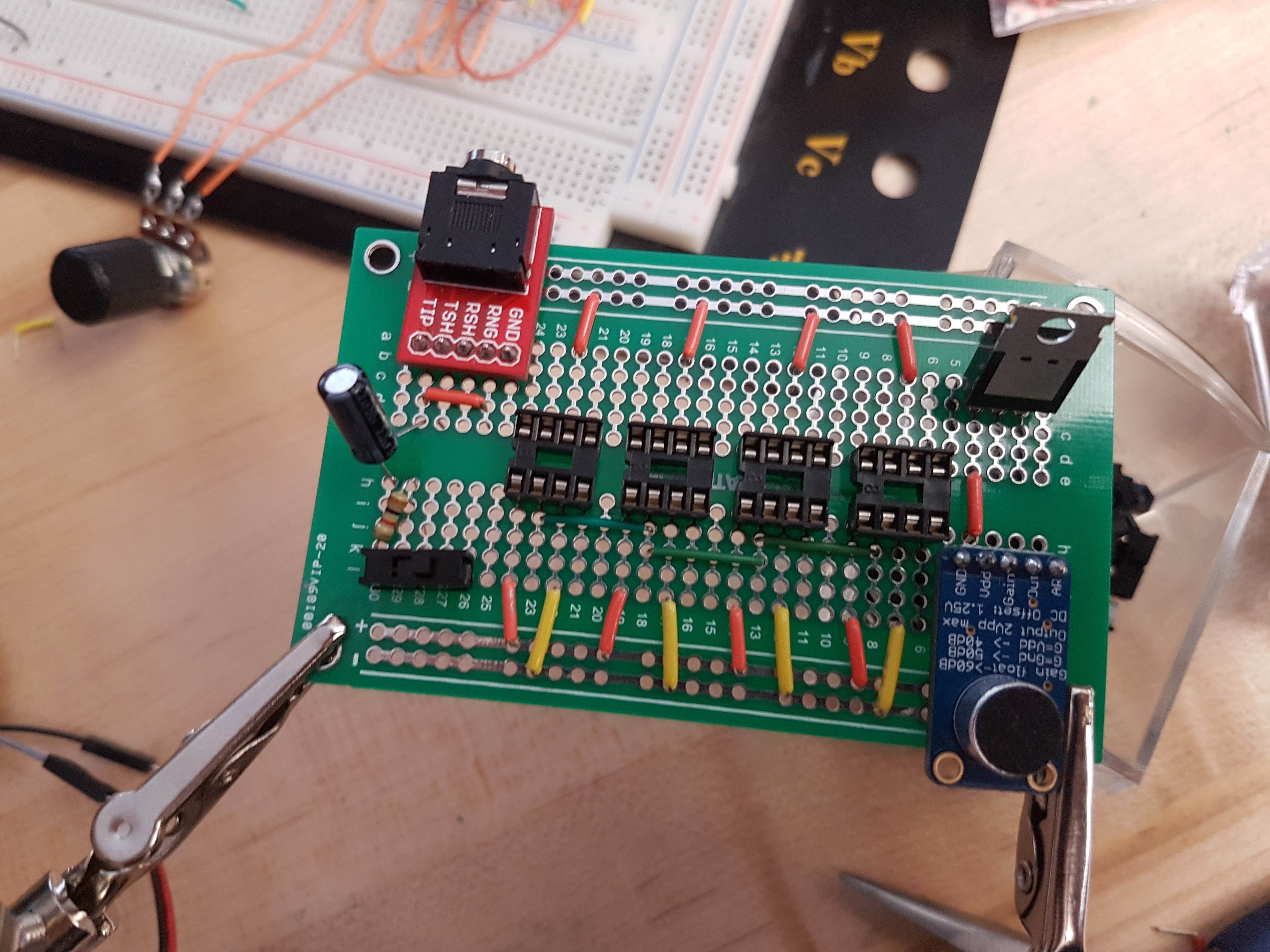
The next step was replacing the speaker output on the broadcaster circuit with LEDs. The more LEDs used the greater the distance the audio was able to broadcast. The final step was soldering the circuit together and adding a switch to change between 3.5mm line in and microphone input.
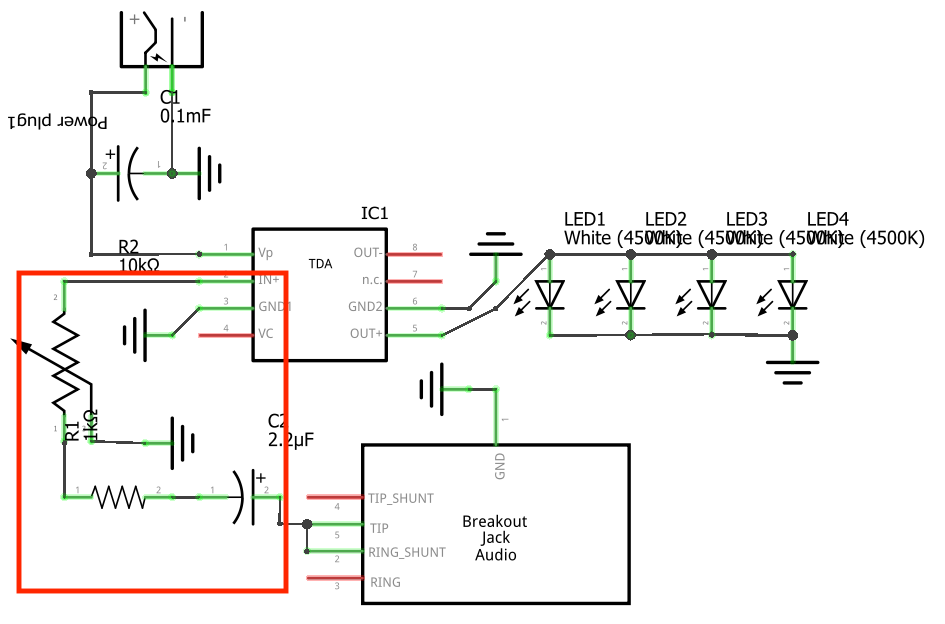
At right is a schematic of the fundamental circuit. The area in the red box is the high-pass filter.
Media
 |  |
| Prototyping OP-Amp circuit | Dry fit before soldering |
|---|---|
 |  |
| Final Photophone broadcaster circuit | Simplified Fritzing diagram |
| Link to YouTube Video: https://youtu.be/s8sXL5Ja8Gs | |
Conclusion
In closing, I am satisfied with the results of this project. I am also exited to develop this project further and make an interactive display for future students. My plan is to incorporate the photophone into a reading lamp and add a sound board that changes the audio being played out of the light. I hope that by making this project interactive it will inspire students to get creative in their ISP projects and think of applications for this technology. I also intend for the display piece to be more polished and attractive than this project. This project has helped me develop knowledge of amplifier circuits and fibre optics. While my final unit did not incorporate fibre optics, I learned a lot about how they function in the prototyping stage where I experimented with them. Ultimately, my work on this project has only just begun and I intend to keep thinking of uses for a photophone circuit.
Reference
"1 Watt Audio Amp." Amplifiercircuit.net, 23 July 2011, http://amplifiercircuit.net/wp-content/uploads/2011/07/1w-audio-amplifier-circuit-based-TDA7052.jpg.
"TDA7052A/AT Datasheet." NXP.com, NXP Semiconductors, July 1994, http://www.nxp.com/docs/en/data-sheet/TDA7052A_AT.pdf.