Challenge 2. Rotary Encoder: Gray Code
Purpose
The purpose of this project is to take input from the rotary encoder and display its value on three 7-segment displays. The rotary encoder outputs its value in gray code, so it must be converted to a binary value. To display this binary value, it must be converted to a binary-coded-decimal (BCD). Transistors must be used to cycle through the 7-segment displays in order to give the appearance of every display being on at once.
| Parts List | |
|---|---|
| 4-Bit Gray-Code Rotary Encoder | 3× 7-Segment Display |
| CD4511BE BCD to 7-Segment Display IC | 4× 1MΩ Resistor |
| 3× 3904 NPN Transistor | 3× 1kΩ Resistor |
| Arduino Uno |
Procedure
This challenge started by wiring the rotary encoder to an existing 7-segment BCD display circuit. The initial circuit consisted of a 4511 IC connected to three 7-segment displays. The displays achieved persistence of vision (POV) by toggling the ground connection through the use of NPN transistors. The wiring of the rotary encoder is nearly the same as that in Challenge 1 Rotary Switch Monitor.
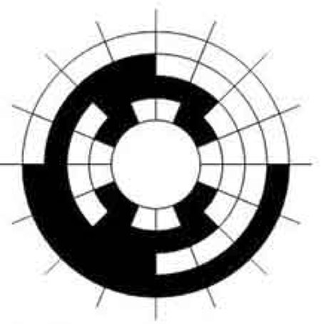
The real difference is in the output from the rotary encoder. Instead of returning a binary number according to the position of the rotor, the encoder used here returns a "Gray code" value. Gray code is very different from binary. Instead of being a "weighted" number system, wherein a change in a specific digit always has the same affect on a number, Gray code is unweighted. This makes it a code instead of a number system. The key feature of Gray code is that between each number only one bit changes value. When using binary, multiple bits often change from a 1 to a 0 while incrementing or decrementing number value. This reduces ambiguity between number states and, in extreme cases, can reduce wear on memory. At right is the bottom view of Gray code rotary encoder, with white squares being zeros and black squares representing ones.
The code does the brunt of the work in this challenge. The code consists of three main parts. First, the program takes input from the rotary encoder attached to PORTD and converts the Gray code to a binary value. Next, the code converts this to a BCD value on r17 and r18. Finally the program displays these values on the 7-segment displays using POV. The code then loops to constantly poll the input states of the rotary encoder.
In the first step of the input portion, the collect function stores the input state of PORTD to a register. It then shifts this register right, as the zero pin of PORTD does not have input, and the first input is instead on pin one. To convert the Gray code to binary, the convert function adds the binary value of the gray code input to the value of the x register and stores this in the z register. Next it queries the value stored at this position in memory. Here it returns a binary value equivalent to the Gray code. This is because the register stores the binary conversion of the Gray code at the index of the direct binary value of the gray code. For example, while Gray code 0b0011 is a two, the direct binary value is three.
Next, the program converts the binary value to a BCD. Beginning at the loop label, the program shifts the input value left through the output registers, carrying the dropped value into each consecutive register. Here the iterate register decrements, as the algorithm must know whether or not the input number is fully converted or not. Next the program checks if the low bit of the first register is greater than or equal to three. The value of this register increases by three if this condition is true. The tens label repeats this step for the high bit of the first register. Instead, however, it checks if the register has a value greater than 80 (0x50) and adds 48 (0x30) if this condition is true. Again, this step repeats under the hundreds label, checking the low bit of the second register and adding three accordingly. Here it jumps back to the loop label. The input value is fully converted to BCD when the iterate register reaches zero.
In the final part, the pov function takes the registers storing the BCD value and outputs the according number to the 4511 BCD to 7-segment display chip. The hundreds register displays first, with output on PORTC. Next, the base pin of the according transistor activates by setting PORTB. After displaying the hundreds digit, the tens digit is displayed by swapping the nibbles of the first register (r17), and repeating the steps for the hundreds register. The transistor select register shifts by one to enable the tens display and disable the hundreds display. Next, r17 swaps nibbles again and the above steps repeat, but for the ones digit. In the final step, the program jumps to the beginning of the program and the process repeats.
Media
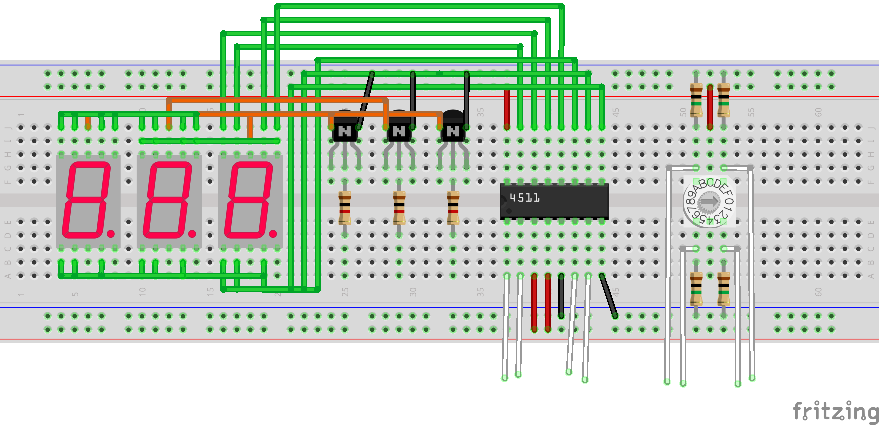 | 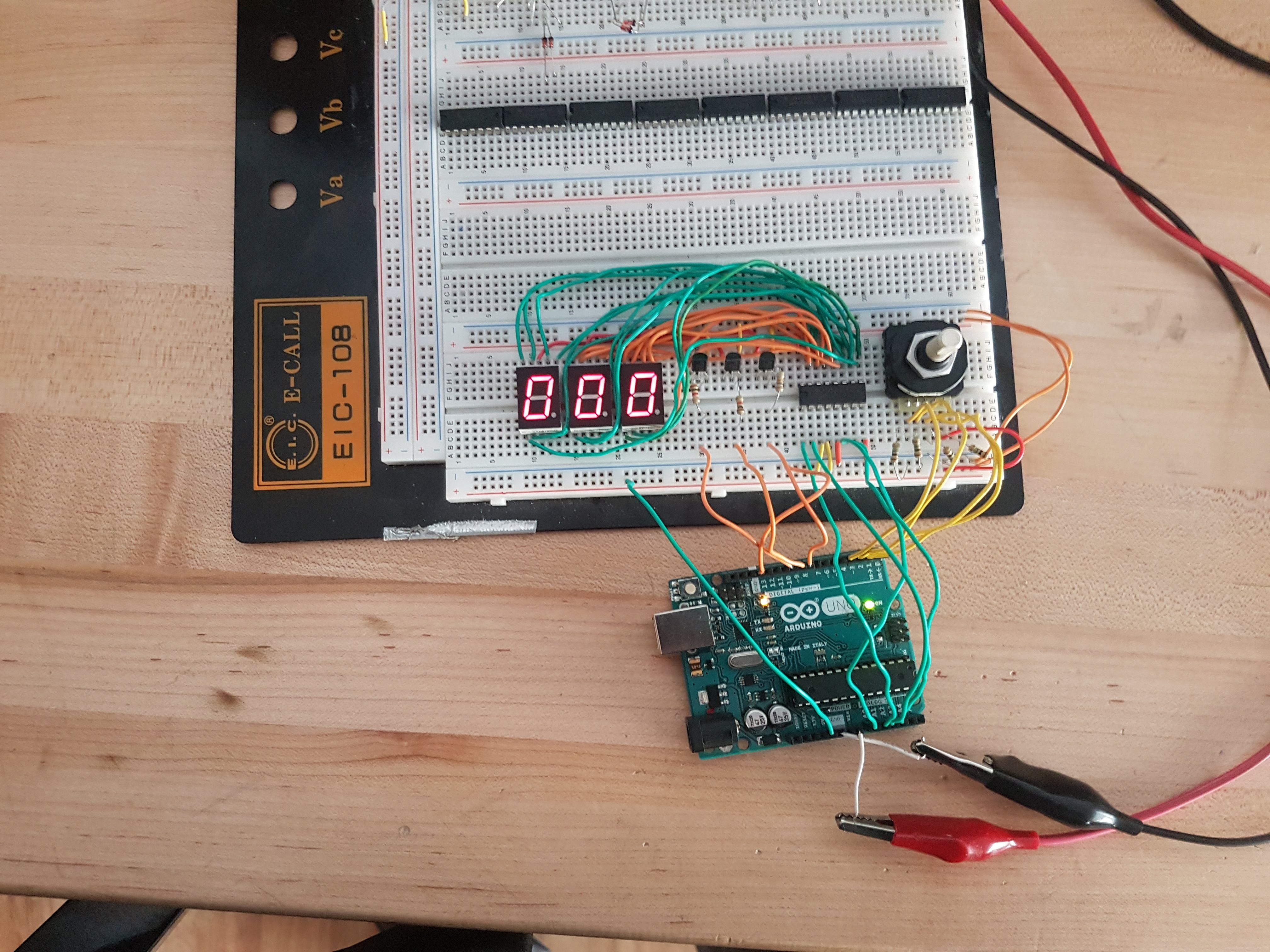 |
| Fritzing diagram | Circuit overview |
|---|---|
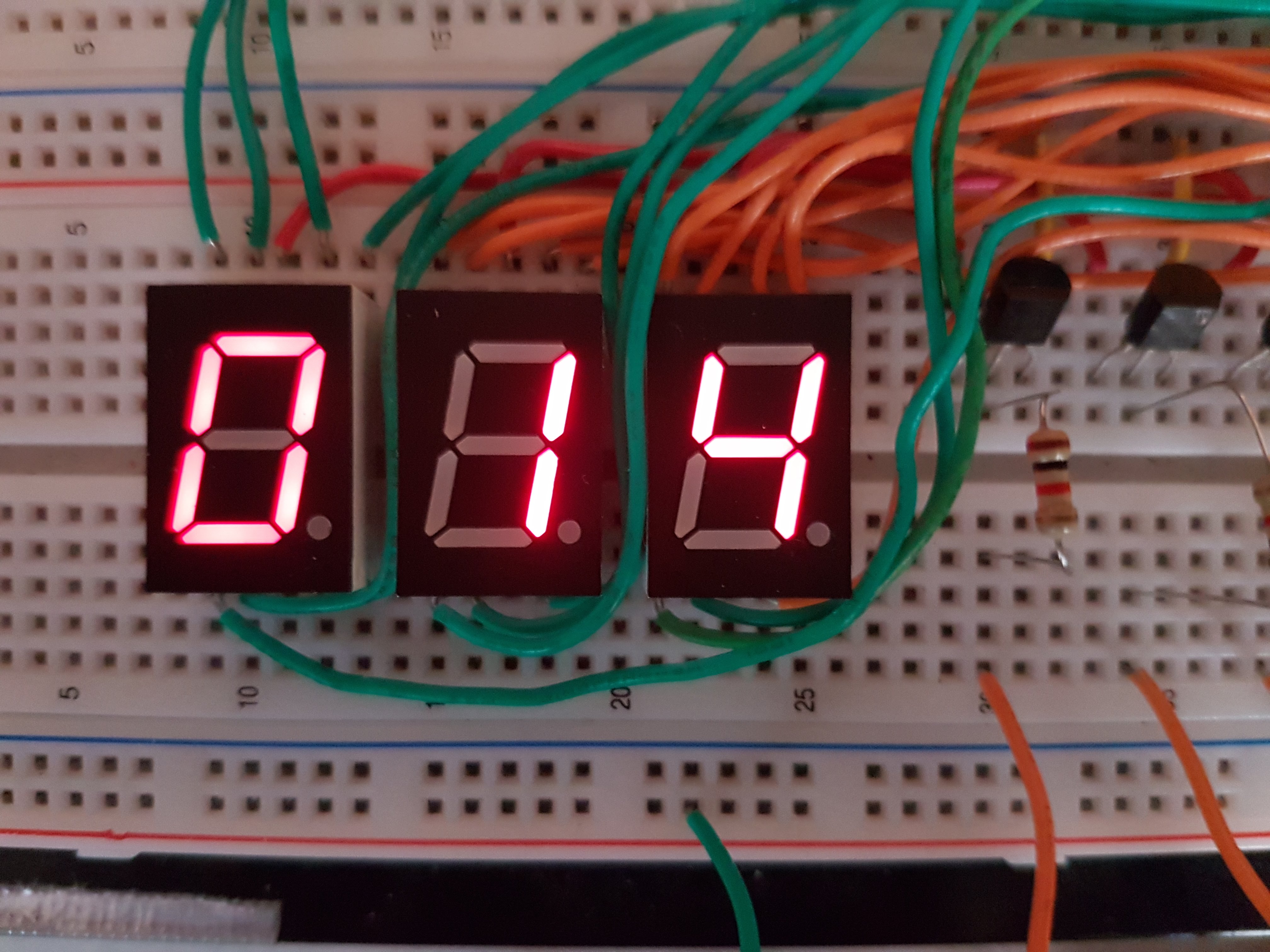 | 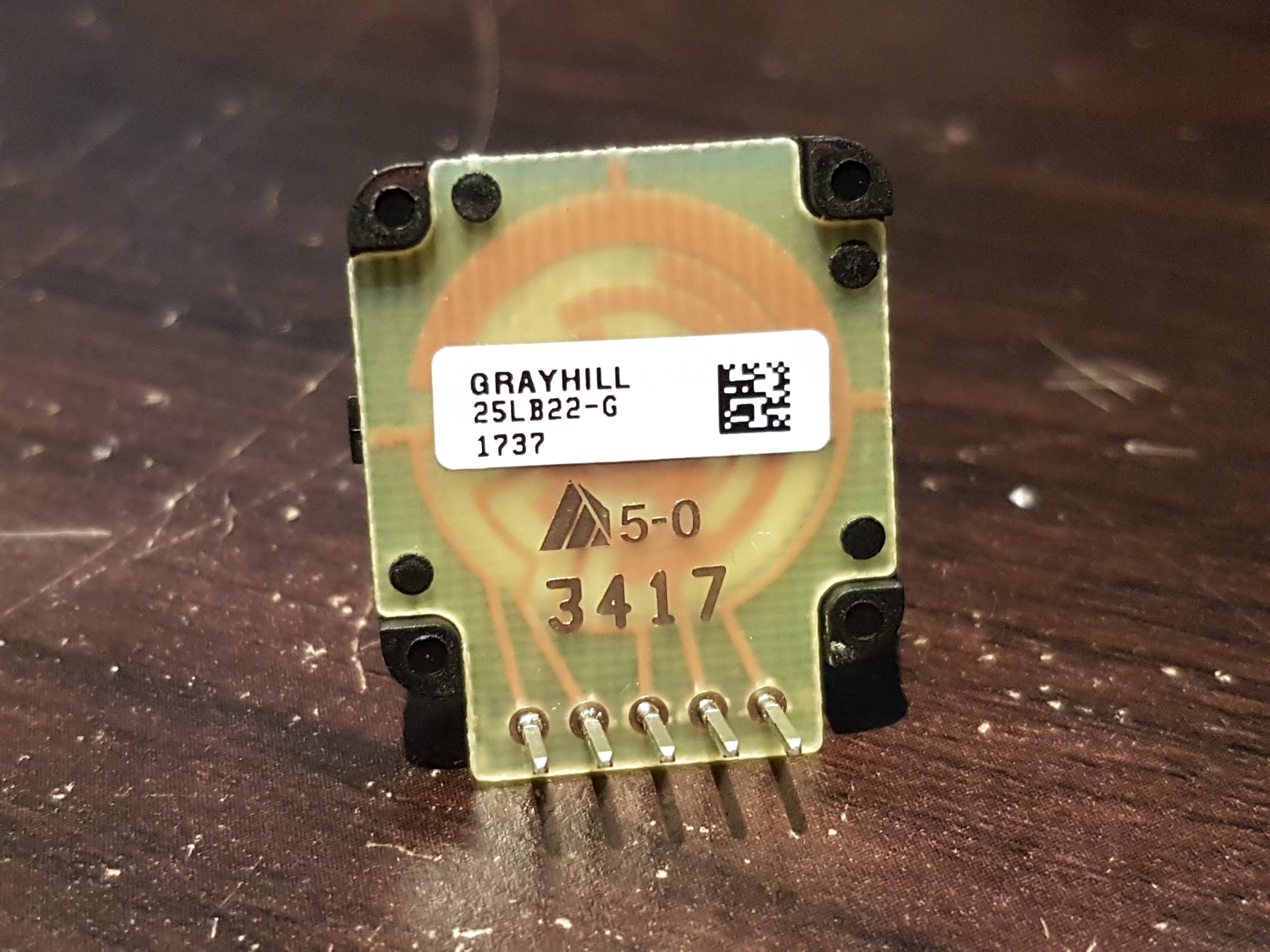 |
| Proper operation showing output 14 | Bottom of rotary encoder |
| Link to YouTube Video: https://youtu.be/K7AFz38Lux8 | |
Code
; GrayCodeChallenge.asm
;
; Created: 2018-01-15 8:57:57 AM
; Author : Ethan McAuliffe
.def    iterate = r24
.def    temp  = r25
.def    three = r23
.def    threeTens = r22

.cseg

.org 0x0000
   rjmp  reset
;segment table format: ;gfab_cde.

.org 0x0010
grayStart:
  .DB   0,1,3,2,7,6,4,5,15,14,12,13,8,9,11,10
grayEnd:

reset:
    ldi   r16, low(RAMEND)      ;ALL assembly code should start by
    out   spl,r16                     ; setting the Stack Pointer to
    ldi   r16, high(RAMEND)     ; the end of SRAM to support
    out   sph,r16                     ; function calls, etc.
    ldi   xl,low(grayStart<<1)  ;position X and Y pointers to the
    ldi   xh,high(grayStart<<1) ;start and end addresses of
    ldi   yl,low(grayEnd<<1)   ; our data table, respectively
    ldi   yh,high(grayEnd<<1)
    movw  z,x                    ;start Z pointer off at the start address of the table.

    ldi r16,0x1E
    out DDRD,r16
    ldi r16,0x07
    out DDRB,r16            ;pins to control transistors
    ldi r16,0x0F
    out DDRC,r16            ;pins to control 7-segment driver

collect:
    clr r16
    clr r17
    clr r18
    in r16,PIND         ;store input from rotary encoder
    lsr r16             ;shift right to get gray code
    movw z,r16          ;move to element the gray code is in binary
    add zl,xl
    lpm r18,z             ;store fetched binary value

convert:
    mov r16,r18
    ldi iterate, 8
    ldi three, 0x03
    ldi threeTens, 0x30
    clr r17
    clr r18

loop:
   rol r16
   rol r17
   rol r18              ;shift value and BCD registers with carry
   dec iterate
   breq pov             ;jump to POV if there are no bits left to convert

   mov temp, r17
   andi temp, 0x0F
   cpi temp, 0x05
   brlo tens        ;skip to tens if value is less than 5
   add r17,three    ;otherwise add three
tens:
   cpi temp, 0x50
   brlo hundreds
   add r17,threeTens
hundreds:
   andi temp, 0x0F
   cpi temp, 0x50
   brlo loop
   add r18, three
rjmp loop

pov:
    out PORTC,r18           ;output hundreds value
    ldi r16,0x04
    out PORTB,r16           ;enable hundreds 7-seg disp
    rcall delay
    lsr r16

    swap r17
    out PORTC,r17           ;output tens value
    out PORTB,r16           ;enable tens 7-seg disp
    rcall delay
    lsr r16

    swap r17
    out PORTC,r17           ;output ones value
    out PORTB,r16           ;enable ones 7-seg disp
    rcall delay
rjmp collect

delay:
; Generated by delay loop calculator
; at http://www.bretmulvey.com/avrdelay.html
;
; Delay 16 000 cycles
; 1ms at 16 MHz

    ldi  r19, 21
    ldi  r20, 199
L1: dec  r20
    brne L1
    dec  r19
    brne L1
ret
Conclusion
To conclude, I am satisfied with the final result of this project. Unfortunately, I was not able to have operational code by the end of the challenge period. After working on my program throughout the week, however, I was able to get a working solution. My initial code was organized properly, but not operational. This challenge has adequately tested my knowledge of assembly code. It has also helped me develop my understanding of Gray code and a broader understanding on conversion algorithms/techniques.
Reference
D'Arcy, Chris. "TEI4M Challenges." ACES, RSGC, 15 Jan. 2018, darcy.rsgc.on.ca/ACES/TEI4M/1718/Challenges.html#2.
Grayhill. "Series 25L." Grayhill.com, Digi-Key, www.grayhill.com/assets/1/7/Mech_Encoder_25L.pdf.