Medium ISP: Word Clock and Weather Predictor
Purpose
The purpose of this project is to create a clock capable of showing the current time, temperature, humidity and short-term forecast in a clean, sleek way. The clock is to read the time off of an Real Time Clock (RTC) IC, read air pressure, humidity and temperature wirelessly from a separate device, and display everything in an easy to understand way. To display the time, words for each five minute interval and each hour are to illuminate. To display the current temperature and relative humidity percentage (%RH), the first ten columns are to light up and show the required digits, similar to a 7-segment display. A "C" and a "%" sign will also illuminate for temperature and %RH respectively. The weather sensor is to be separate from the clock and communicate with the main clock via a NRF24L01+ wireless communication IC.
| Parts List | |
|---|---|
| 2× Arduino Uno | 2× NRF24L01+ Wireless Chip |
| 93× Red-Green BiColour LEDs | 4'×2' Medium Density Fibreboard (MDF) |
| Clear Acrylic Sheet | Piano Black Plastic Sheet |
| BME280 I2C or SPI Temperature Humidity Pressure Sensor | DS1307 I2C Real Time Clock |
Procedure
 This project begins with designing the main clock face. It is paramount that the clock face contains all the necessary words to display any five minute interval of time. This step also requires careful planning of the order that words will appear to ensure readability (top to bottom, left to right) and that there is adequate spacing between each word. Each line must also have the same number of characters, and the "C" and "%" characters must be present only in the far-right column. Creation of the design initially began in a text file, and was then transferred to a table in a word document to add colour. Creation of the final design required using a CAD program, in this case ViaCAD 3D, to ensure proper spacing of characters. Mr. Elia helped greatly with this. The final step in designing the clock face was sending the design files off to be laser cut in acrylic and plastic. Assembly began when the laser cut pieces arrived. Gluing the characters into place meant ensuring that the block shape of each was clear acrylic, and the inner "floating" parts of the characters were the same black plastic as the rest of the clock face. This allowed for avoiding a stencil font while still maintaining readability.
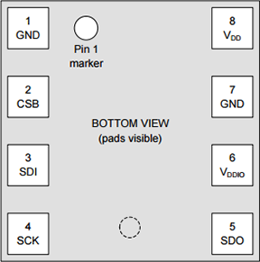
Creating the wireless weather sensor was the next step. This began with reading the datasheet to understand where to find data on the IC and how to access it using Serial Peripheral Interface (SPI). Pictured on the previous page is the pinout for the BME280 sensor. It is a surface mount device.
SPI works similar to serial communication, but with the added benefit of the slave device (in this case the BME280 sensor) being able to contact the master device as well (in this case the Arduino Uno). Unlike I2C, it requires 4 pins. See Wireless Communication: Temperature Data Logging for more information on Serial Communication. SPI is the chosen protocol in this case because it means using only one communication protocol to interact with the wireless transmitter and the weather sensor.
Configuring the BME280 chip is important so that that reports the values as desired. The sensorConfig() function configures the sensor by performing a reset, identifying how often the sensor is to record information, and how sensitive the sensor should be to sudden changes in values. It also initiates getCompensationData().
The data from the BME280 chip requires processing before it can accurately display the time. This is because each individual chip has different sensitivities to the environment. The manufacturer, Bosch, solves this problem by storing "compensation data" in specific registers on the chip. The getCompensationData() function in the Remote Sensor code obtains this data. The getCompensationData() function is only called once as the compensation data never changes. A special struct called compData stores this data because some values have different lengths, some are "signed" and some are "unsigned". This was problematic as the datasheet provided incorrect information on which characters were signed or unsigned. by comparing the individual compensation data readouts to those of the Adafruit library, it was easy to deduce which were incorrect.
Signed characters use format called Two's Compliment to store their values. Using an 8-bit byte as an example, two's compliment has the ability to store a value ranging from -128 to 127 inclusive. Two's compliment works by accepting a positive integer from 0-128, then performing a bitwise "NOT", and adding 1. This value now represents a negative integer. The computer can tell that the value is negative, because the most significant bit of binary integer is a "1". For more information on bitwise, see the BiColour LED Matrix project.
Recording the uncompensated, or "raw", data from the sensor happens after reading the compensation data. The getRawData() function obtains said data and stores it in a struct called rawData. This data is then run through specific algorithms defined in the datasheet, which use the compensation data recorded earlier, to get the temperature in degrees Celsius, the pressure in Pascals, and the relative humidity percentage. These algorithms are temp(), pressure() and humidity() for temperature, pressure and humidity respectively. Each returns a value of specific size for easy formatting and transmission using the transmit() function.
The transmit() function compacts the temperature, pressure and humidity data into one unsigned, 64-bit integer, and transmits it wirelessly via the NRF24L01+. The program then uses the deepSleep() function to enter the peripherals into low power mode, wait, and then turn the sensor back on. This function uses SPI to write to a specific register on the BME280 sensor requesting that it enter sleep mode.
The clock code first uses I2C to intercept the current hour and minute from the DS1307 RTC. This code is works almost identically to that used in the Nixie Tube Clock project. The updateTime() function obtains this time and stores it in a struct called currentTime for easy access. This function also converts the 24-hour time stored on the RTC into 12-hour time for the clock to display.
The receive() function then looks for available data from the remote sensor, formats the recieved 64 bit, unsigned integer into temperature, pressure and humidity again, and then stores it in a struct called senseData.
The current time is then formatted into specific words and printed to the serial monitor via the printTimeAndData() function. This function first reads the current minute and maps it to a value from 0-12, inclusive. This value is then used to query the minuteText[] array and determine what text to show for the current minute. Next the function determines if the clock should display "TO" or "PAST" the hour. The clock only switches to "TO" after 35 minutes of the current hour have elapsed. The mapped value is again used to determine this. The final step in showing the current time is displaying the appropriate hour in relation to the current time. For this the current hour value minus one (because arrays are zero indexed) index of thehourText[] array prints to the serial monitor. If the minutes, however, are greater than 35, the clock must display the future hour as the clock will now show "TO" instead of "PAST". As such the index of the current hour is directly indexed into the hourText[] array. Finally the function prints the data intercepted from the remote sensor to the serial monitor. This includes whether or not the weather is improving, or worsening.
The isWeatherImproving() function uses an average of the pressure from each five minute interval over the past hour plus the current pressure and compares it against the oldest pressure reading. If the average is less than the oldest reading, pressure is decreasing and the weather is getting worse. Otherwise, the weather is improving and the function returns true.
While simple at first, numerous obstacles faced the construction of this clock later on. Cutting the perfectly square back plate of the clock and wooden borders of the face plate was the first step. Gluing the cardstock baffles which ensured no light bleed from neighbouring characters followed. This ensured that the clock would be easy to read. Problems arose in the final steps when planning out a NeoPixel LED matrix for backlighting, as the NeoPixels were non-functional. BiColour Red/Green LEDs replaced the NeoPixels after a last-minute visit to a hardware store. Unfortunately, however, the ATmega328P does not have enough ports to control the 93 LED matrix, and as such, the clock cannot function. Painting the clock and gluing the faceplate in position were the final steps. A possible solution to this problem would be a larger Arduino device to control the entire matrix, or (the better option) to purchase a working strip of NeoPixels.
Media
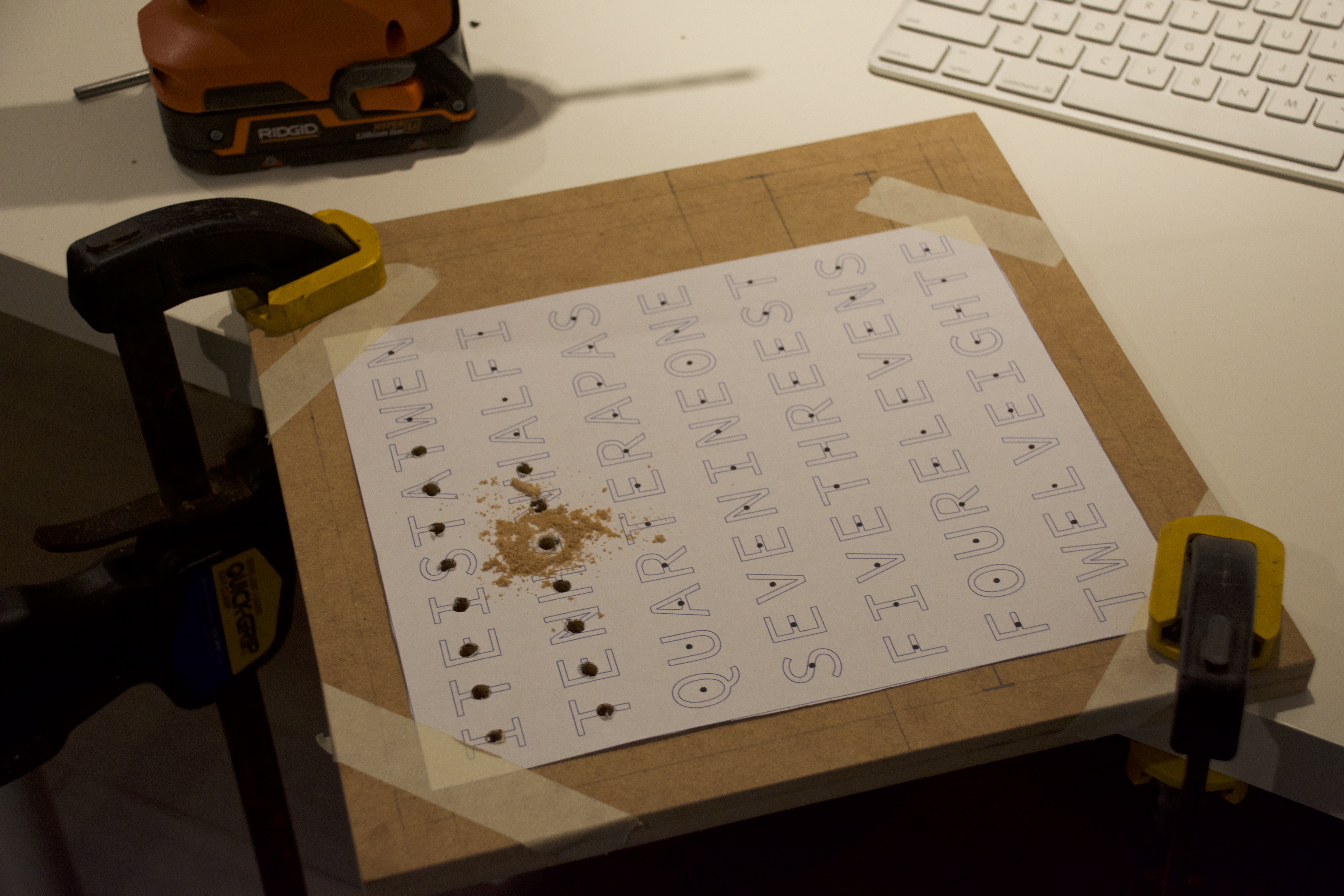 | 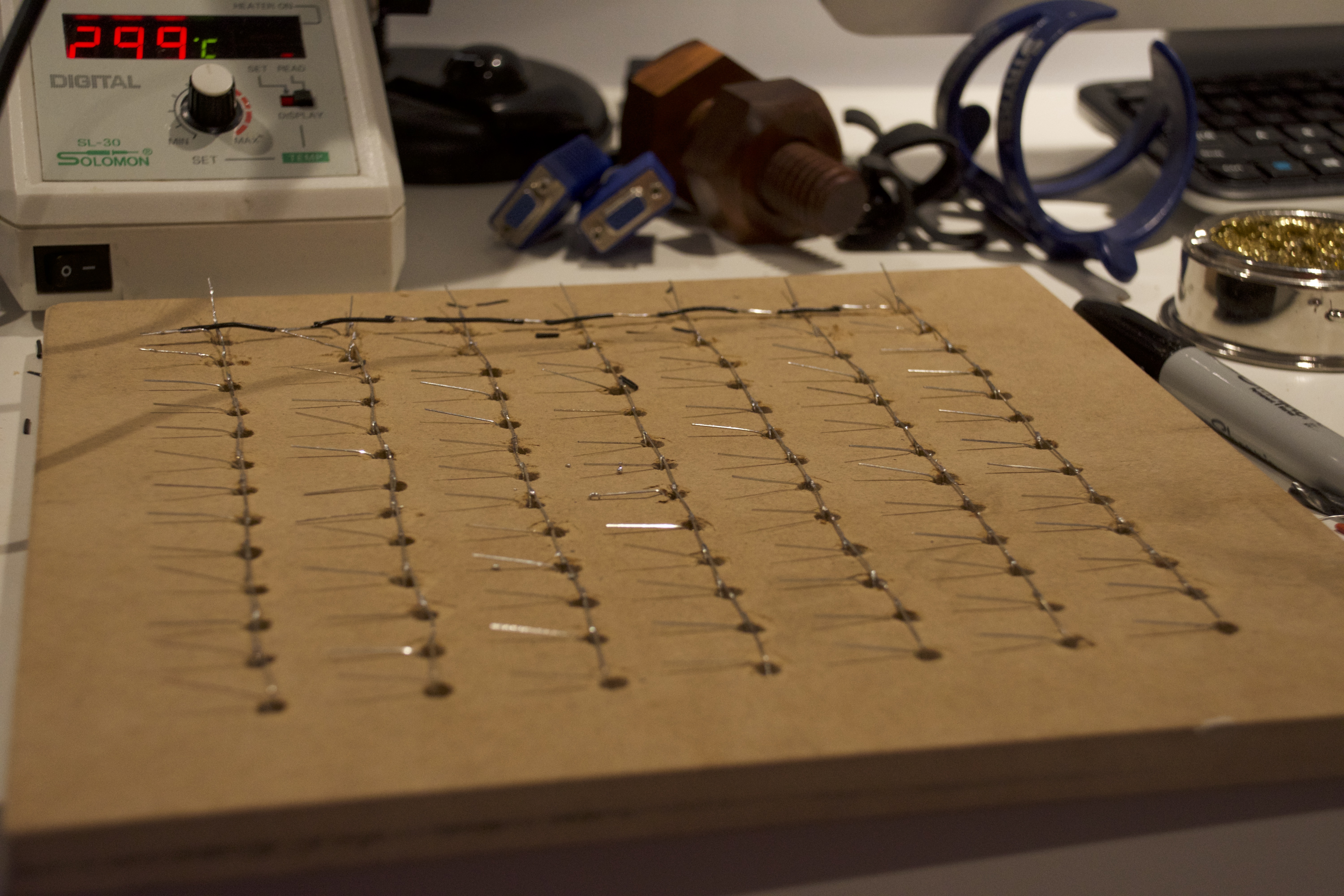 |
| Drilling holes for LEDs | Soldering LED matrix |
|---|---|
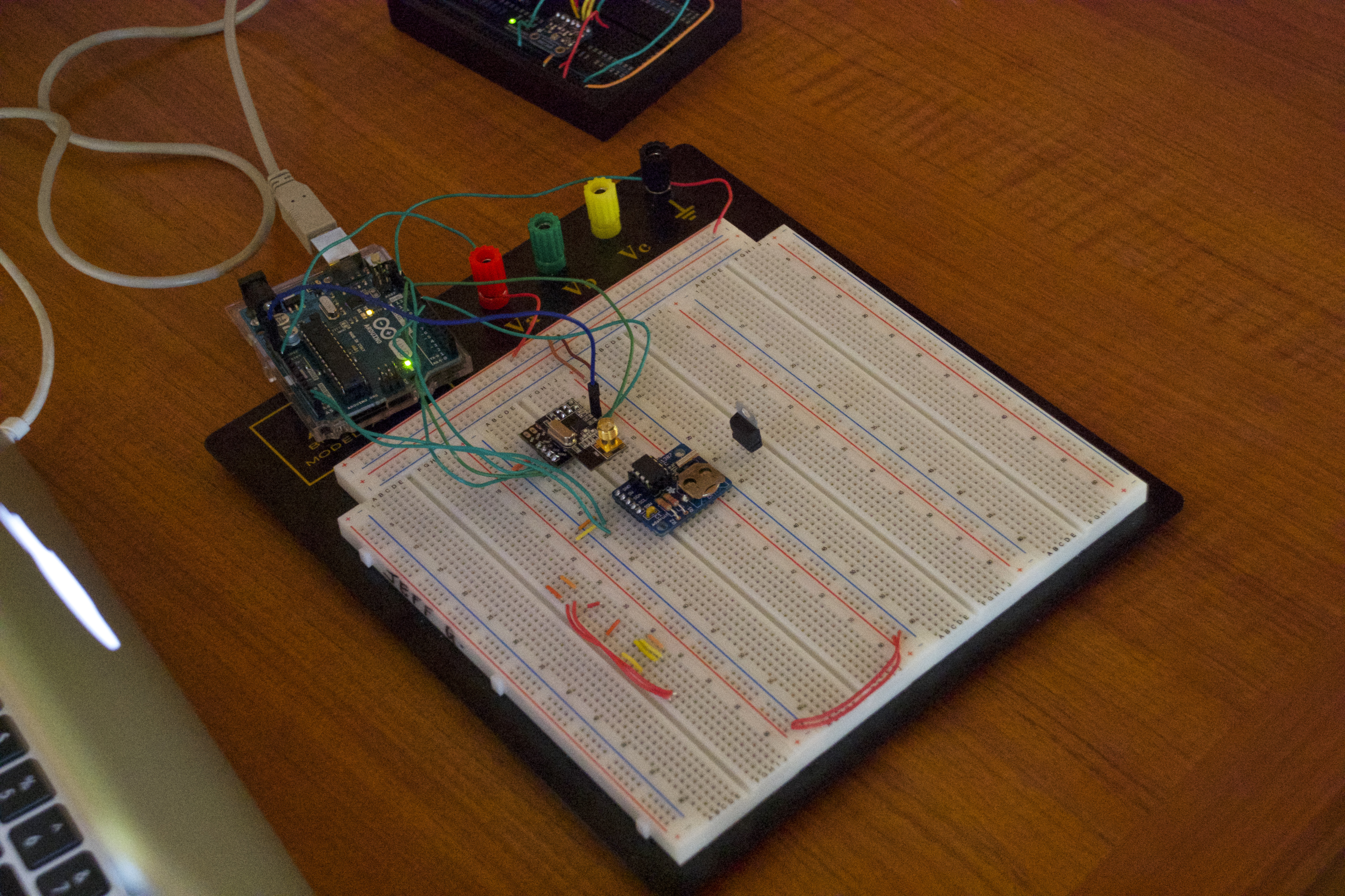 | 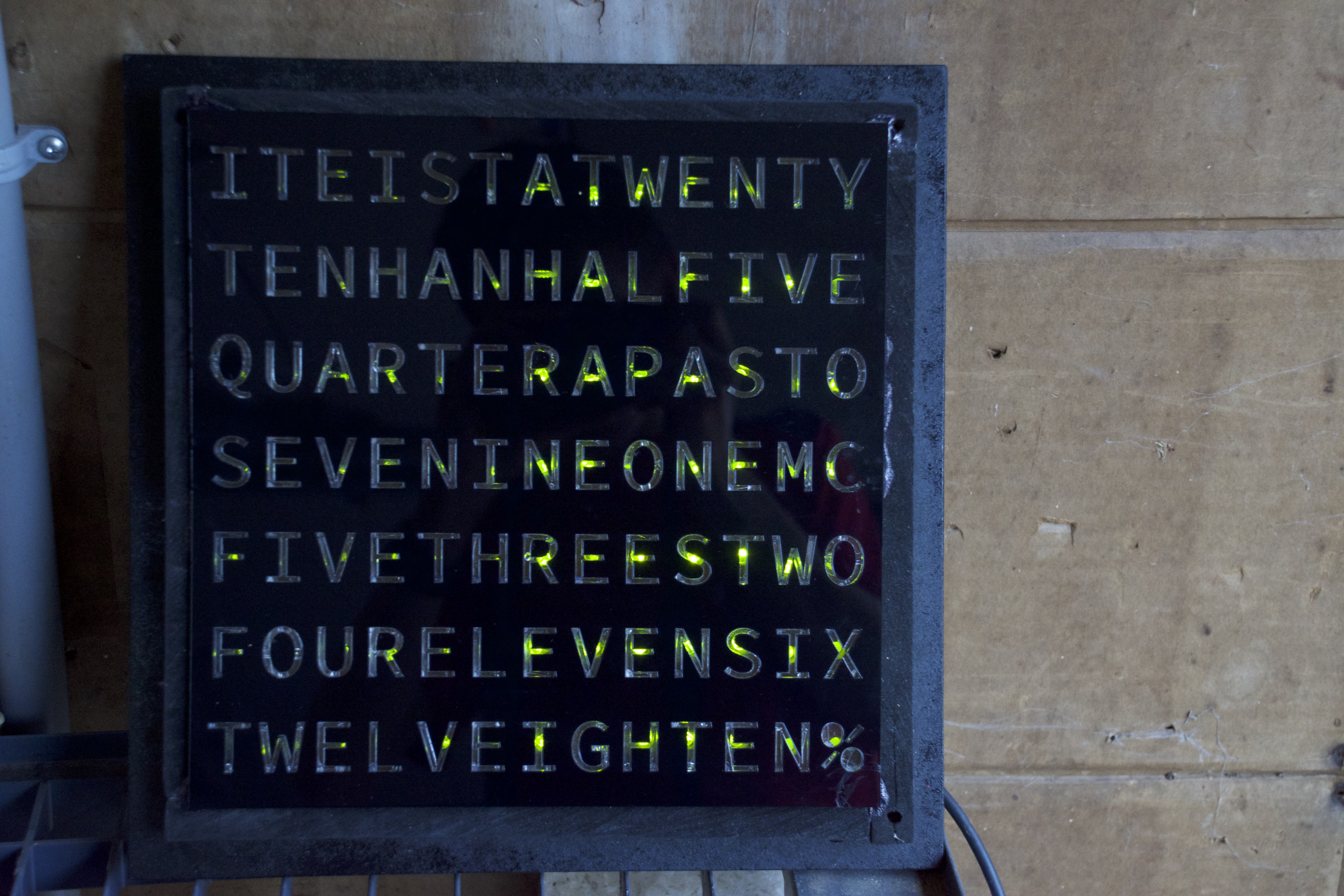 |
| Testing Main clock module without matrix | Illuminated Clock Face |
| Link to YouTube Video: https://youtu.be/pIHCYQPU6w8 | |
Code
Main Clock Code
#include <Wire.h>
#include <nRF24L01.h>
#include <printf.h>
#include <RF24.h>
#include <RF24_config.h>

#define RTC_ADDRESS 0x68

RF24 radio(9, 10);
uint8_t addresses[][6] = {"3g8wM", "0Us9x"};
uint64_t data;
bool goodWeather;
String hourText[] = {"ONE", "TWO", "THREE", "FOUR", "FIVE", "SIX", "SEVEN", "EIGHT", "NINE", "TEN", "ELEVEN", "TWELVE"};
String minuteText[] = {"", "FIVE", "TEN", "A QUARTER", "TWENTY", "TWENTY FIVE", "A HALF", "TWENTY FIVE", "TWENTY", "A QUARTER", "TEN", "FIVE", ""};
uint32_t pressureAverage[13];
uint8_t durationThroughHour;

struct SENSORDATA {
  int8_t temp;
  float pressure;
  uint8_t hum;
};

struct CURRENT_TIME {
  uint8_t hours;
  uint8_t minutes;
};

SENSORDATA senseData;
CURRENT_TIME currentTime;

void setup() {
  Serial.begin(9600);
  radio.begin();
  Wire.begin();

  radio.setChannel(99);

  radio.openReadingPipe(1, addresses[0]);
  radio.startListening();
}

void loop() {
  updateTime();
  receive();
  printTimeAndData();
}

void receive() {
  if (radio.available()) {
    radio.read(&data, sizeof(uint64_t));
    senseData.temp = (int8_t)(data >> 40);
    senseData.pressure = ((data >> 8) & 0xFFFFFFFF) / 25600.00;
    senseData.hum = (uint8_t)data & 0xFF;
    pressureAverage[durationThroughHour] = (uint32_t)senseData.pressure;
  }
}

void updateTime() {
  Wire.beginTransmission(RTC_ADDRESS);
  Wire.write(1); //prepare rtc to be read from
  Wire.endTransmission();
  Wire.requestFrom(RTC_ADDRESS, 7);
  while (!Wire.available());
  currentTime.minutes =  readTime(Wire.read() & 0x7f); //minute
  uint8_t hours = readTime(Wire.read() & 0x3f);
  if (hours > 12) {
    hours = hours - 12;
  }
  if (hours == 0) {
    hours == 12;
  }
  currentTime.hours = hours;
}

bool isWeatherImproving() {
  uint32_t pressureSum;
  for (uint8_t ii; ii < 13; ii++) {
    pressureSum += pressureAverage[ii];
  }
  if (pressureSum / 13 > (pressureAverage[12 - durationThroughHour])) {
    return false;
  } else {
    return true;
  }
}

void printTimeAndData() {
  Serial.print("It is ");
  durationThroughHour = map(currentTime.minutes, 0, 60, 0, 12);
  Serial.print(minuteText[durationThroughHour]);
  if (durationThroughHour != 0) {
    if (durationThroughHour <= 6) {
      Serial.print(" PAST ");
    } else {
      Serial.print(" TO ");
    }
  }
  if (currentTime.minutes < 35) {
    Serial.print(hourText[currentTime.hours - 1]);
    Serial.print(" ");
  } else {
    Serial.print(hourText[currentTime.hours]);
    Serial.print(" ");
  }
  Serial.print("  --  ");
  Serial.print(senseData.temp);
  Serial.print("* C ");
  Serial.print(senseData.pressure);
  Serial.print(" hPa ");
  Serial.print(senseData.hum);
  Serial.print("% RH ");
  if (isWeatherImproving() == true) {
    Serial.print("IMPROVING ");
  } else {
    Serial.print("GETTING WORSE ");
  }
  Serial.println();
}

uint8_t readTime(uint8_t input) { //makes time human readable (0-60 and 0-24)
  return ((input / 16 * 10) + (input % 16));
}
Remote Sensor Code
#include <SPI.h> // for interfacing with the data sensor
#include <nRF24L01.h>
#include <printf.h>
#include <RF24.h>
#include <RF24_config.h>

#define SENSORSS 10
#define SENSORSPEED 500000

RF24 radio(7, 8);
uint8_t addresses[][6] = {"3g8wM", "0Us9x"};
int32_t currentTemp;

struct SCOMP {
  uint16_t T1;
  int16_t T2;
  int16_t T3;
  uint16_t P1;
  int16_t P2;
  uint16_t P3;
  uint16_t P4;
  int16_t P5;
  int16_t P6;
  uint16_t P7;
  int16_t P8;
  uint16_t P9;
  uint8_t H1;
  int16_t H2;
  uint8_t H3;
  int16_t H4;
  int16_t H5;
  int8_t H6;
};
struct RAWDATA {
  uint32_t uPress;
  uint32_t uTemp;
  uint32_t uHum;
};

RAWDATA rawRead;
SCOMP compData;

void setup() {
  pinMode(SENSORSS, OUTPUT);
  digitalWrite(SENSORSS, HIGH);

  radio.begin();
  SPI.begin();

  ACSR = B10000000;
  ADCSRA = ADCSRA & B01111111;
  DIDR0 = DIDR0 | B00111111;

  radio.setPALevel(RF24_PA_MAX);
  radio.setChannel(99);
  radio.openWritingPipe(addresses[0]);

  sensorConfig();
}

void loop() {
  getRawData();
  transmit(temp(rawRead.uTemp), pressure(rawRead.uPress), humidity(rawRead.uHum));
  deepSleep();
}

int8_t temp(int32_t inTemp) {//returns temp in degrees celcius int8_t
  int32_t var1, var2;
  var1 = ((((inTemp >> 3) - ((int32_t)compData.T1 << 1))) * ((int32_t)compData.T2)) >> 11;
  var2 = (((((inTemp >> 4) - ((int32_t)compData.T1)) * ((inTemp >> 4) - ((int32_t)compData.T1))) >> 12) * ((int32_t)compData.T3)) >> 14;
  currentTemp = var1 + var2;
  return round(((currentTemp * 5 + 128) >> 8) / 100.00);
}

int32_t pressure(int32_t inPress) {//returns pressure in int_32
  temp(rawRead.uTemp);
  int64_t var1, var2, p;
  var1 = ((int64_t)currentTemp) - 128000;
  var2 = var1 * var1 * (int64_t)compData.P6;
  var2 = var2 + ((var1 * (int64_t)compData.P5) << 17);
  var2 = var2 + (((int64_t)compData.P4) << 35);
  var1 = ((var1 * var1 * (int64_t)compData.P3) >> 8) + ((var1 * (int64_t)compData.P2) << 12);
  var1 = (((((int64_t)1) << 47) + var1)) * ((int64_t)compData.P1) >> 33;

  if (var1 == 0) {
    return (uint32_t)0; // avoid exception caused by division by zero
  }

  p = 1048576 - inPress;
  p = (((p << 31) - var2) * 3125) / var1;
  var1 = (((int64_t)compData.P9) * (p >> 13) * (p >> 13)) >> 25;
  var2 = (((int64_t)compData.P8) * p) >> 19;
  p = ((p + var1 + var2) >> 8) + (((int64_t)compData.P7) << 4);
  return (uint32_t)p;
}

uint8_t humidity(uint32_t inHum) {//returns percent relative humidity int8_t
  int32_t v1;
  v1 = (currentTemp - ((int32_t)76800));
  v1 = (((((inHum << 14) - (((int32_t)compData.H4) << 20) - (((int32_t)compData.H5) * v1)) + ((int32_t)16384)) >> 15) * (((((((v1 * ((int32_t)compData.H6)) >> 10) * (((v1 * ((int32_t)compData.H3)) >> 11) + ((int32_t)32768))) >> 10) + ((int32_t)2097152)) * ((int32_t)compData.H2) + 8192) >> 14));
  v1 = (v1 - (((((v1 >> 15) * (v1 >> 15)) >> 7) * ((int32_t)compData.H1)) >> 4));
  v1 = (v1 < 0) ? 0 : v1;
  v1 = (v1 > 419430400) ? 419430400 : v1;
  return round((v1 >> 12) / 1024.00);
}

void sensorConfig() {
  digitalWrite(SENSORSS, LOW);
  SPI.beginTransaction(SPISettings(SENSORSPEED, MSBFIRST, SPI_MODE0));
  SPI.transfer(0x60);//initiate write to reset register
  SPI.transfer(0xB6);//performs soft reset
  delay(25);
  SPI.endTransaction();
  digitalWrite(SENSORSS, LOW);
  SPI.beginTransaction(SPISettings(SENSORSPEED, MSBFIRST, SPI_MODE0));
  SPI.transfer(0x75);//initiate write to config
  SPI.transfer(0x04);//0.5ms delay, filter x2
  SPI.transfer(0x72);//initiate write to ctrl_hum
  SPI.transfer(0x01);//set filtering to 1x
  SPI.transfer(0x74);//initiate write to ctrl_meas
  SPI.transfer(0xB7);//normal mode
  digitalWrite(SENSORSS, HIGH);
  SPI.endTransaction();
  delay(25);
  getCompensationData();
}

void getRawData() {
  SPI.beginTransaction(SPISettings(SENSORSPEED, MSBFIRST, SPI_MODE0));
  digitalWrite(SENSORSS, LOW);
  SPI.transfer(0xF7);
  //pressure
  rawRead.uPress = SPI.transfer(0x00);
  rawRead.uPress <<= 8;
  rawRead.uPress |= SPI.transfer(0x00);
  rawRead.uPress <<= 8;
  rawRead.uPress |= SPI.transfer(0x00);
  rawRead.uPress >>= 4;
  //temperature
  rawRead.uTemp = SPI.transfer(0x00);
  rawRead.uTemp <<= 8;
  rawRead.uTemp |= SPI.transfer(0x00);
  rawRead.uTemp <<= 8;
  rawRead.uTemp |= SPI.transfer(0x00);
  rawRead.uTemp >>= 4;
  //humidity
  rawRead.uHum = SPI.transfer(0x00);
  rawRead.uHum <<= 8;
  rawRead.uHum |= SPI.transfer(0x00);
  SPI.endTransaction();
  digitalWrite(SENSORSS, HIGH);
}

void transmit(int8_t tempD, uint32_t pressD, uint8_t humD) { //sends data to the main clock
  uint64_t transmissionData;
  transmissionData = tempD;
  transmissionData <<= 32;
  transmissionData |= pressD;
  transmissionData <<= 8;
  transmissionData |= humD;

  radio.powerUp();
  delay(6);
  radio.write(&transmissionData, sizeof(uint64_t));
}

void wakeSensor() {
  digitalWrite(SENSORSS, LOW);
  SPI.beginTransaction(SPISettings(SENSORSPEED, MSBFIRST, SPI_MODE0));
  SPI.transfer(0x74);
  SPI.transfer(0xB7);
  delay(30);
  digitalWrite(SENSORSS, HIGH);
  SPI.endTransaction();
}

void sensorSleep() {
  digitalWrite(SENSORSS, LOW);
  SPI.beginTransaction(SPISettings(SENSORSPEED, MSBFIRST, SPI_MODE0));
  SPI.transfer(0x74);
  SPI.transfer(0xB4);
  delay(30);
  digitalWrite(SENSORSS, HIGH);
  SPI.endTransaction();
}

void deepSleep() { //powers down peripherals and ATmega328
  sensorSleep();
  radio.powerDown();
  delay(20000);
  wakeSensor();
}

void getCompensationData() {//populates compData struct
  digitalWrite(SENSORSS, LOW);
  SPI.beginTransaction(SPISettings(SENSORSPEED, MSBFIRST, SPI_MODE0));
  SPI.transfer(0x88);
  //Temperature
  compData.T1 = (SPI.transfer(0x00) << 8 | SPI.transfer(0x00));
  compData.T1 = (compData.T1 >> 8 | compData.T1 << 8);
  compData.T2 = (SPI.transfer(0x00) << 8 | SPI.transfer(0x00));
  compData.T2 = (compData.T2 >> 8 | compData.T2 << 8);
  compData.T3 = (SPI.transfer(0x00) << 8 | SPI.transfer(0x00));
  compData.T3 = (compData.T3 >> 8 | compData.T3 << 8);
  //Pressure
  compData.P1 = (SPI.transfer(0x00) << 8 | SPI.transfer(0x00));
  compData.P1 = (compData.P1 >> 8 | compData.P1 << 8);
  compData.P2 = (SPI.transfer(0x00) << 8 | SPI.transfer(0x00));
  compData.P2 = (compData.P2 >> 8 | compData.P2 << 8);
  compData.P3 = (SPI.transfer(0x00) << 8 | SPI.transfer(0x00));
  compData.P3 = (compData.P3 >> 8 | compData.P3 << 8);
  compData.P4 = (SPI.transfer(0x00) << 8 | SPI.transfer(0x00));
  compData.P4 = (compData.P4 >> 8 | compData.P4 << 8);
  compData.P5 = (SPI.transfer(0x00) << 8 | SPI.transfer(0x00));
  compData.P5 = (compData.P5 >> 8 | compData.P5 << 8);
  compData.P6 = (SPI.transfer(0x00) << 8 | SPI.transfer(0x00));
  compData.P6 = (compData.P6 >> 8 | compData.P6 << 8);
  compData.P7 = (SPI.transfer(0x00) << 8 | SPI.transfer(0x00));
  compData.P7 = (compData.P7 >> 8 | compData.P7 << 8);
  compData.P8 = (SPI.transfer(0x00) << 8 | SPI.transfer(0x00));
  compData.P8 = (compData.P8 >> 8 | compData.P8 << 8);
  compData.P9 = (SPI.transfer(0x00) << 8 | SPI.transfer(0x00));
  compData.P9 = (compData.P9 >> 8 | compData.P9 << 8);
  //Humidity
  digitalWrite(SENSORSS, HIGH);
  digitalWrite(SENSORSS, LOW);
  SPI.transfer(0xA1);
  compData.H1 = SPI.transfer(0x00);
  digitalWrite(SENSORSS, HIGH);
  digitalWrite(SENSORSS, LOW);
  SPI.transfer(0xE1);
  compData.H2 = (SPI.transfer(0x00) << 8 | SPI.transfer(0x00));
  compData.H2 = (compData.H2 >> 8 | compData.H2 << 8);
  compData.H3 = SPI.transfer(0x00);
  compData.H4 = (SPI.transfer(0x00) << 4) | (SPI.transfer(0x00) & 0xF);
  digitalWrite(SENSORSS, HIGH);
  digitalWrite(SENSORSS, LOW);
  SPI.transfer(0xE5);
  compData.H5 = (SPI.transfer(0x00) >> 4) | (SPI.transfer(0x00) << 4);
  compData.H6 = SPI.transfer(0x00);
  digitalWrite(SENSORSS, HIGH);
  SPI.endTransaction();
}
Conclusion
In conclusion, this project was unsuccessful; however, it can be easily completed given the correct, fully operational, parts. I did enjoy working with ViaCAD to create a clean, accurate final product, and while it may not work as intended, it does look quite nice. This project taught me to always test your components before you leave the lab for a long weekend. While I am wholeheartedly disappointed with the results this far, I am optimistic that I can get this project to achieve its intended purpose. While it was quite difficult, I enjoyed working with only the SPI library to communicate with the BME280 chip as it taught me more about the SPI protocol, how data is stored in peripherals, and how to read (and find issues with) datasheets. I have alerted Bosch of the issue with their datasheet and they have yet alerted me of a change. From the issue with the NeoPixels, I learned how to think quickly and produce a final project with some resemblance to the intended final product. I hope to bring what I learned about communication protocols, sensors, data compensation algorithms and limitations of certain products with me for utilization in future projects.
Reference
"BME280." Bosch Sensortec, Bosch, 26 Oct. 2015, http://ae-bst.resource.bosch.com/media/_tech/media/datasheets/BST-BME280_DS001-11.pdf. Accessed 22 May 2017.
Burgess, Phillip. "Adafruit NeoPixel Überguide." Adafruit NeoPixel Überguide, Adafruit, 30 Aug. 2013, http://learn.adafruit.com/adafruit-neopixel-uberguide/overview. Accessed 22 May 2017.