BiColour LED Matrix
Purpose
The purpose of this project is to learn about low-level port manipulation using the ATtiny84 and a homemade bicolour LED matrix display. The LED matrix is to show a unique and challenging pattern. This project incorporates persistence of vision (POV), switching quickly between red and green to create a yellow colour and code that uses bitwise operators. The animations used will consist of a square counting down from four to zero, then a red dot flashing in sync with a buzzer; a series of firework-like explosion animations wherein the LEDs flash outwards in a cross from an origin; and a yellow sunrise and sunset animation.
| Parts List | |
|---|---|
| ATtiny84 Through-Hole Microcontroller | 16 × Red-Green BiColour LEDs |
| Piezo buzzer | AVR Pocket Programmer |
| AVR Programmer Breakout Board | Heat-Shrink Tubing |
| 4 × Male to Female Jumper Wires |
Procedure
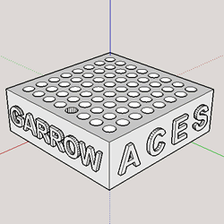
This project begins by soldering the LED matrix together using the 3D-Printed matrix jig (seen bottom right). The arrangement of the LEDs requires them to be in a particular orientation as to connect all the short pins and long pins together. They must be in this arrangement so that the code can address individual LEDs. Heat shrink tubing on each of the anode pins prevents them from short-circuiting with the bare cathode pins soldered beneath and displaying a unwanted pattern. Building the matrix requires the testing of each LED to ensure operation and prevent non-functional "pixels" on the matrix. Coloured heat shrink tubing added to the ends of the matrix pins differentiate the anode pins of each colour.
The code consists of four separate patterns: countDownSquare(), explodeMatrix(), sunrise(),sunset(). Code uploading utilizes the AVR Pocket Programmer.
 To begin, the `countDownSquare()` function displays a 2×2 square of green LEDs in the middle of the matrix. The function then uses POV to iterate through a series of display outputs. The POV used in this project utilizes the ability to set each individual port on each individual bus to input or output using the Data Direction Register (DDR). When a pin is set to output, it is either ground or VCC. When it is set to input, however, it is essentially "hanging" and will not ground or supply any voltage. This is how it is possible to individually address LEDs. The function continues the countdown, and then shows a blinking red LED in conjunction with a buzzer.
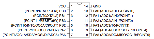 The `explodeMatrix()` function is a special loop that calls the main `fireworks()` function with every individual LED as an origin point. The `fireworks()` function iterates through a loop itself where it fills the matrix with a specific colour, but uses the DDR to disable particular LEDs. The function uses the logical OR operator (see Project 2) on each individual bit (called bitwise) to calculate the required value in the DDR and show only the requested LED. By adding the loop variable to the specified `startingLEDY` and `startingLEDX`, the loop uses POV to light up LEDs in a outward moving "cross" pattern, thus simulating a firework-like explosion.
Finally, the sunrise() function utilises the sunriseDDR[] array to demonstrate that arrays can store patterns. First, the program iterates through a while() to ensure that specific display values appear for an accurate duration of time. The countDownSquare() function uses a similar loop to display POV patterns. The while() loop iterates through each element setting DDRA equal to the value of said element. Using the sunriseFrames variable in the loop prevents it from exceeding the maximum length of the array and breaking the pattern. To finish, the code iterates through the sunriseDDR[] array in reverse to show the sunset animation. The code then loops through the four patterns again.
Media
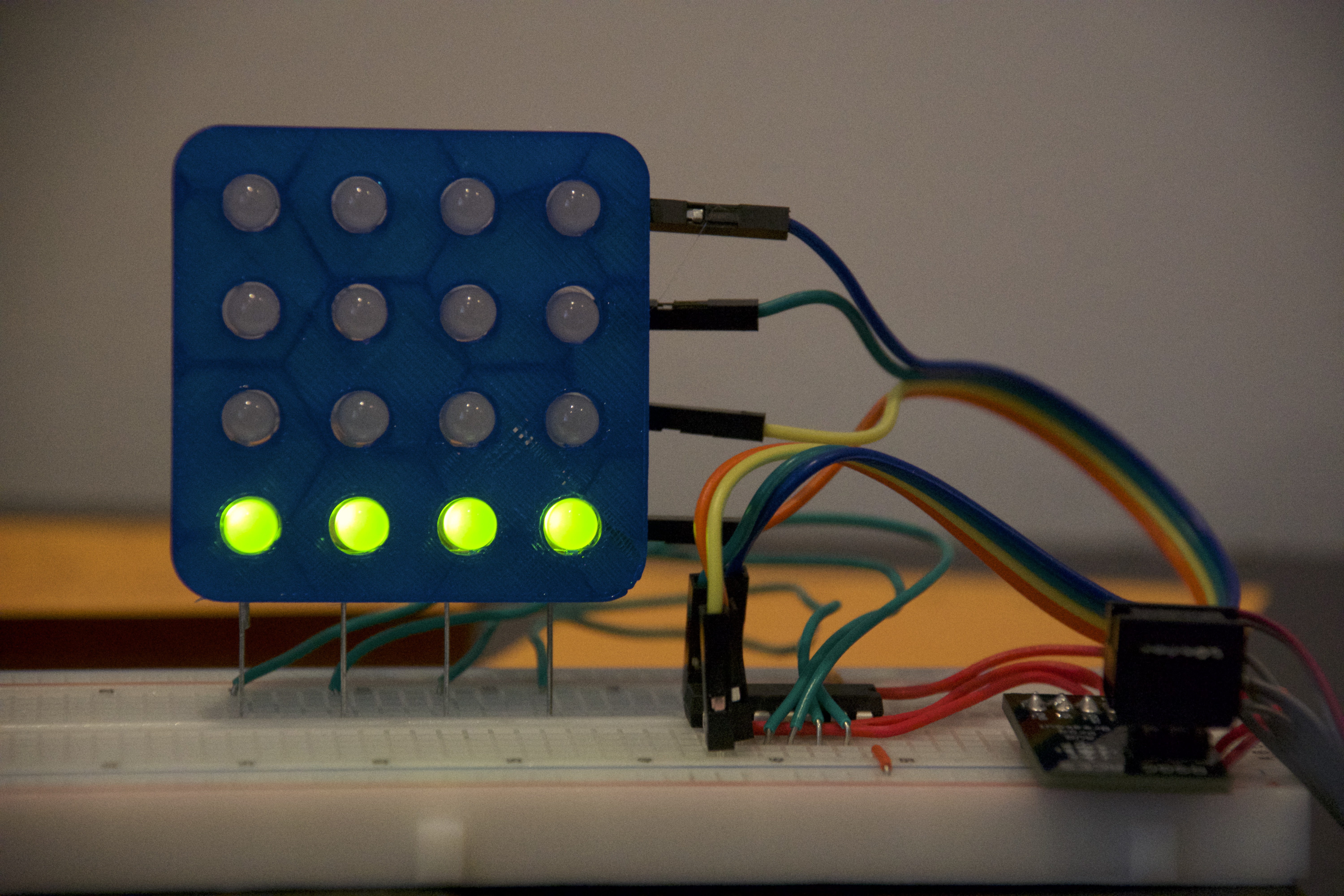 |  |
| Testing patterns on the matrix | countDownSquare() animation |
|---|---|
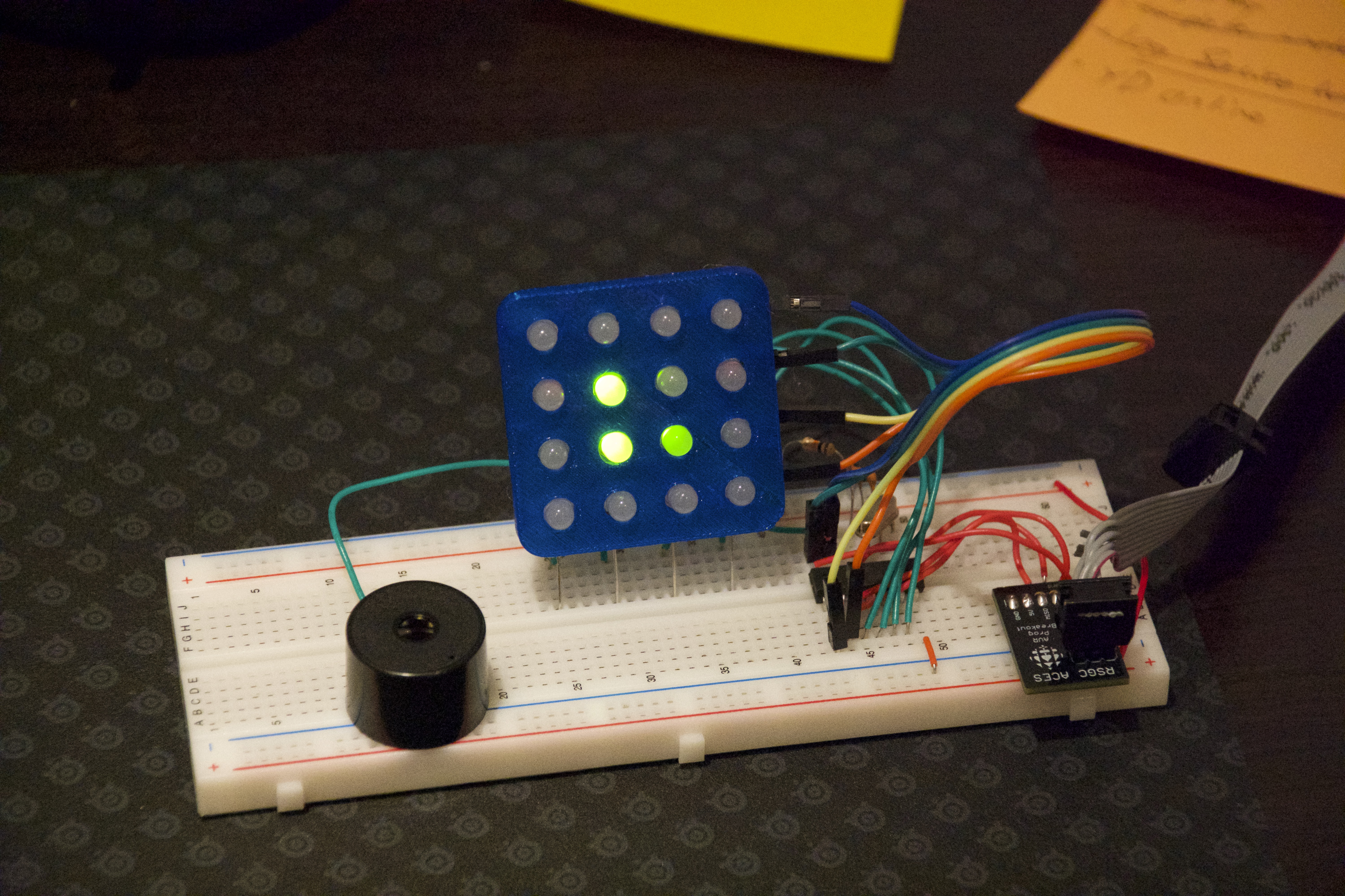
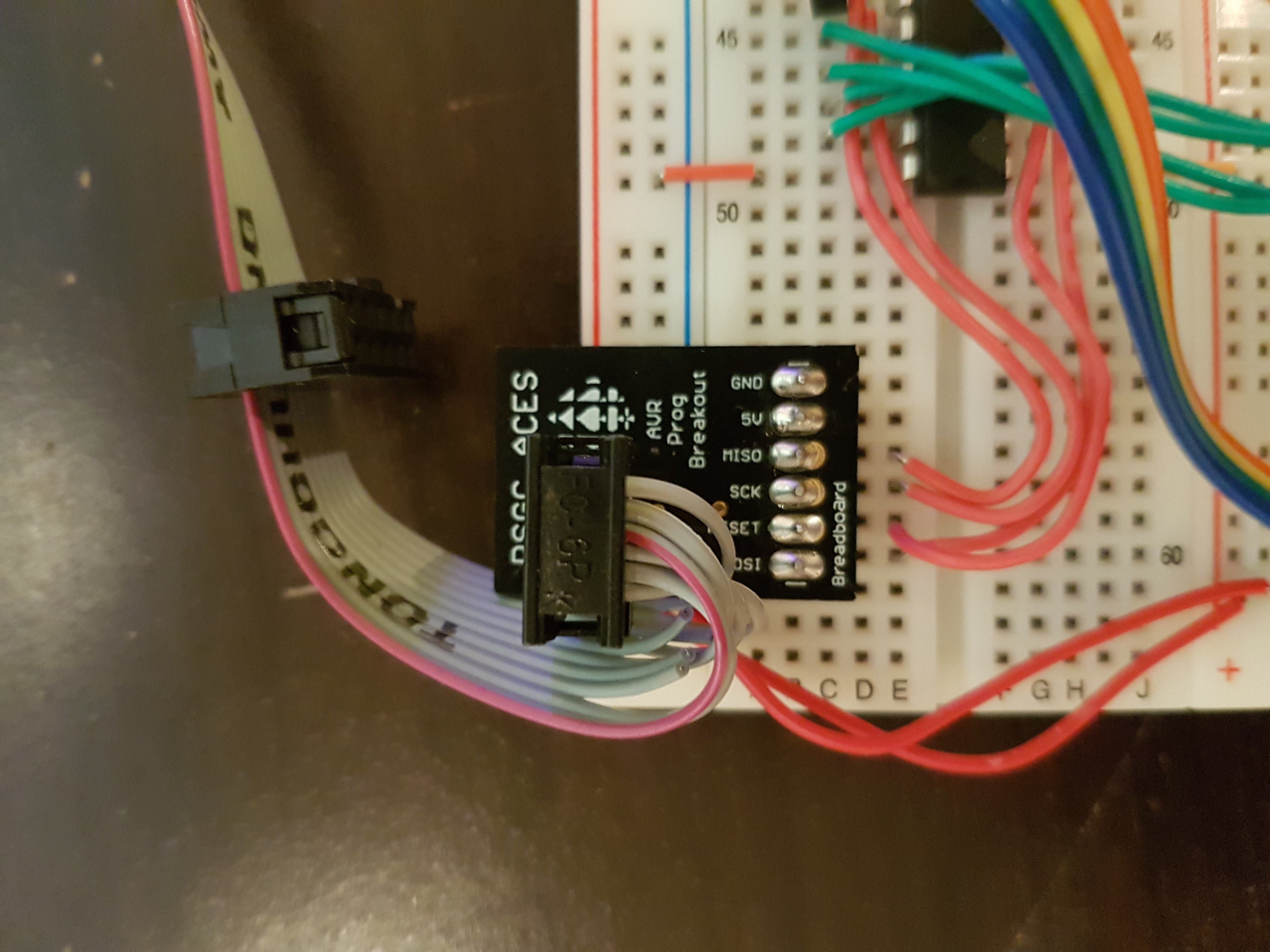 | 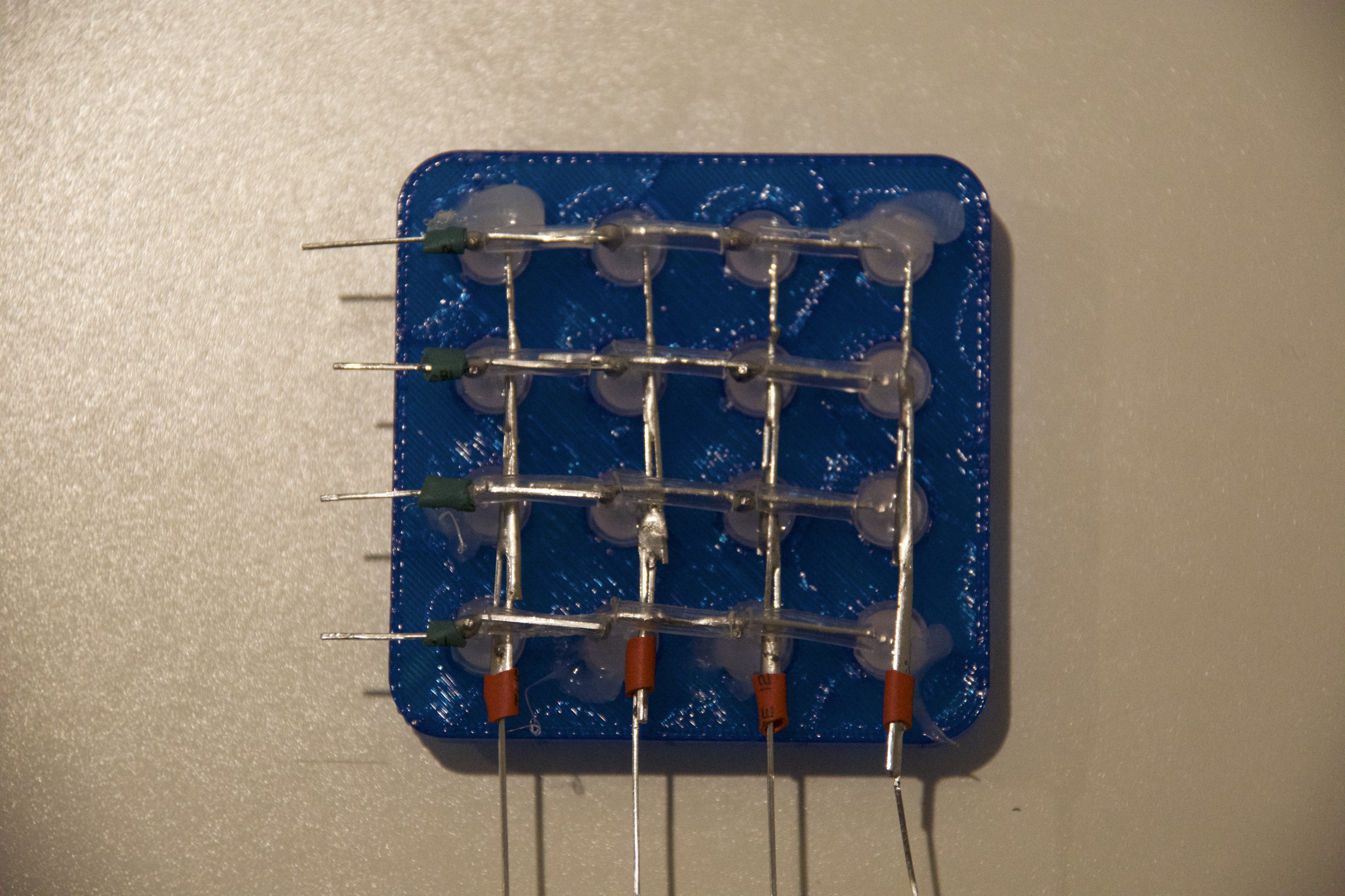 |
| AVR Programmer Breakout Board properly assembled | Final solder job of the BiColour LED Matrix |
| Link to YouTube Video: https://youtu.be/hrjuC2itXW4 | |
Code
#define RED 1

uint8_t sunriseDDR[] = {0x16, 0x36, 0x36, 0x66, 0xC6};//sunrise value array
uint8_t sunriseFrames = sizeof(sunriseDDR) / sizeof(uint8_t); //calculates length of sunrise array in bytes

void setup() {
  DDRA = 0xFF;//preemptively enables output for all matrix ports
  DDRB = 1 << PORTB2;//enables specific port on PORTB for buzzer
}

void loop() {
  countDownSquare(100);
  explodeMatrix();
  sunrise(100);
  sunset(100);
}

void countDownSquare(uint16_t countSpeed) {
  DDRA = 0x66;
  PORTA = 0x60; //full green square
  delay(countSpeed);
  uint16_t povTime = millis();
  while (povTime + 200 >= millis()) { //shows POV of 3 dots in centre of matrix
    DDRA = 0x22;
    PORTA = 0x20; //bottom left green dot
    DDRA = 0x64;
    PORTA = 0x60; //two green line left
  }
  DDRA = 0x64;//shows 2 dots on left side of matrix
  delay(countSpeed);
  DDRA = 0x44;// shows upper left dot
  delay(countSpeed);
  DDRA = 0x44; // keeps red dot in sync with other dots to be displayed
  PORTA ^= 0xFF; //invert colours of top left dot
  DDRA ^= 1 << PORTA2;
  for (uint8_t i; i < 8; i++) {
    PORTB ^= 1 << PORTB2;//turns on and off the buzzer
    DDRA ^= 1 << PORTA2; //turn on and off the top left dot
    delay(countSpeed);
  }
  DDRB = 0x00; //turn off port as interference from other ports can cause noise in the buzzer
}

void firework(uint8_t explosionSpeed, uint8_t startingLEDY, uint8_t startingLEDX) {
  matrix(RED);
  for (uint8_t i = 0; i <= 4; i++) {
    uint16_t povDuration = millis() + explosionSpeed;
    while (povDuration >= millis()) { // uses POV and loop to show "explosion" animation where lit LEDs move out in a cross from the original LED
      DDRA = 1 << startingLEDY + i | 1 << startingLEDX;
      DDRA = 1 << startingLEDY - i | 1 << startingLEDX;
      DDRA = 1 << startingLEDY | 1 << startingLEDX + i;
      (startingLEDX - i) < 0 ? DDRA = 0x00 : DDRA = (1 << startingLEDY | 1 << startingLEDX - i); // if conditional is not used, the LED linked to PORTA0 will stay on, as negatives are not accepted
    }
  }
}

void matrix(uint8_t colour) { //sets matrix either all green or all red
  colour == 1 ? PORTA = 0x0F : PORTA = 0xF0;
}
void explodeMatrix() { //runs through a loop of firework animations; one animation per led on the matrix
  for (uint8_t i = 0; i <= 3; i++) {
    for (uint8_t j = 4; j <= 7; j++) {
      firework(40, j, i);
    }
  }
}

void sunrise(uint16_t duration) { // animates sunrise array
  PORTA = 0x0F;
  for (uint8_t i = 0; i < sunriseFrames; i++) {
    uint16_t povTime = millis() + duration;
    while (povTime > millis()) {
      DDRA = sunriseDDR[i];//loops through array and displays appropriate value
      PORTA ^= 0xFF;
    }
  }
}

void sunset(uint16_t duration) {
  PORTA = 0x0F;
  for (uint8_t i = sunriseFrames - 1; i >= 0; i--) {
    uint16_t povTime = millis() + duration;
    while (povTime > millis()) {
      DDRA = sunriseDDR[i];//loops through array and displays appropriate value
      PORTA ^= 0xFF;
    }
  }
  DDRA = 0x00;
}
Conclusion
In conclusion, I found this project a good learning opportunity that taught me a lot about low-level microcontroller code. This project helped me understand how the microcontroller interprets the functions that I write to it in normal Arduino code. It gave me a certain level of respect for those who write the functions that help beginners learn the basics of coding and keep them motivated. This project also taught me the "low-level" equivalent of LED matrices, wherein the LEDs have to be arranged in a certain way and the leads have to be kept separate in order to have the matrix work as intended. I am happy to have overcome the challenges I had in this project and am excited to bring my newfound knowledge with me for use in future endeavours.
Reference
D'Arcy, Chris. "2016-2017 TEI3M Challenges - BiColor LED Matrix." RSGC ACES, RSGC, http://darcy.rsgc.on.ca/ACES/TEI3M/1617/Challenges.html#BiColorLEDMatrix. Accessed 29 Apr. 2017.