Wireless Communication: Temperature Data Logging
Purpose
The purpose of this project is to use the NRF24L01 wireless communication chip to send data from one arduino to another. The transmitting arduino is to gather data from an I2C thermometer. The transmitter should incorporate power saving features. The receiving arduino is to store the temperature data in EEPROM, and display the current temperature on a scale from -20°C to 80°C, on a bar graph.
| Parts List | |
|---|---|
| 2× NRF24L01+ Wireless Chip | 2× Arduino Uno |
| Soldered Bar Graph Board | TC74 I2C Digital Thermometer |
| 2× 22KΩ Resistor | 4× Male to Female Ribbon Cables (4×1) |
Procedure
This project began after completing the ASCII character transmission project, wherein an arduino transmits the ASCII value of a character is another arduino which displays the value, in binary, on a bar graph. The idea was to create a transmit/receive pair of devices where one connected to a battery to be useful in remote areas, and the other could record data received.
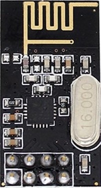
 Completing the wiring the circuit was next. The NRF24L01 chip (image on next page) connects to the SPI serial pins of the arduino, as well as a defined slave select pin and a special pin used to verify data transmission. The TC74 thermometer connects to the defined serial clock and serial data pins of the transmitter arduino. The shift register on the bar graph connects to a defined set of 3 pins: serial data, serial clock and latch. More information on shift registers can be found in my Nixie Tube Clock project.
Serial communication works by first grounding a slave select pin to select the device that data will transmit/receive data; this is called the slave device. Then, a constant pulse starts on the serial clock pin. This allows the two devices to be in sync and always know when a byte is transferring. Data is then sent from the master (the device controlling the slave) to alert the slave device that it is going to have data written or read from it. The master out slave in (MOSI) line is to communicates this. In response, the slave device uses the master in slave out (MISO) pin to relay the requested data back to the device, or the slave receives more data on the MOSI line.
 Next, the writing of the code commenced. The transmitter uses the `readTemp()` function to receive the current temperature from the I2C thermometer and store it in memory. The `radio.write()` function transmits this temperature to over wireless communication to the receiver. To purpose of the `powerSave()` function is to conserve power for longer battery life. It works by taking a defined number of seconds that the user wished the device to sleep for, and turns off the radio chip for that duration of time. While off, the NRF24L01 consumes ~900nA of power, vs 15mA while communicating. Code in the `setup()` function serves to turn off the analog to digital converter (ADC) device on the ATmega328p, thus conserving even more power.
The receiver code waits for the transmitter to send the temperature data using the if (radio.available()) statement. Received data gets displayed on the serial monitor, stored in EEPROM, then mapped and shown on the bar graph using the displayTemp() function. The displayTemp() function works by receiving an unsigned integer, determining how many sections to display on a bar graph, depending on said integer, and shifting out a number that will display the required amount of bar graph sections.
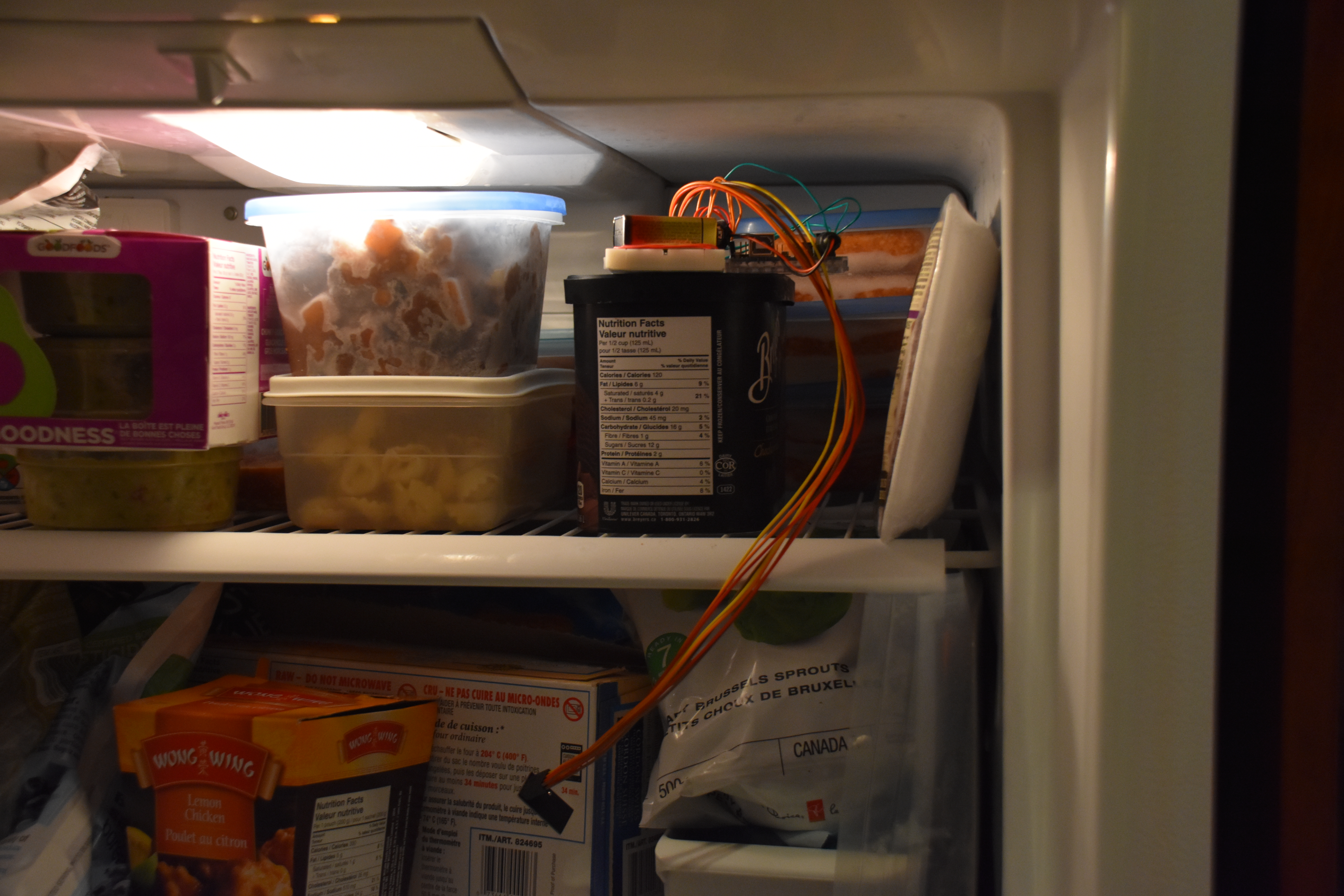
The next step is testing the circuit. The circuit is first placed in a freezer (see picture on previous page) to record negative temperature, and then heated using a blow dryer or similar device to ensure operation at higher temperatures.
Media
 | 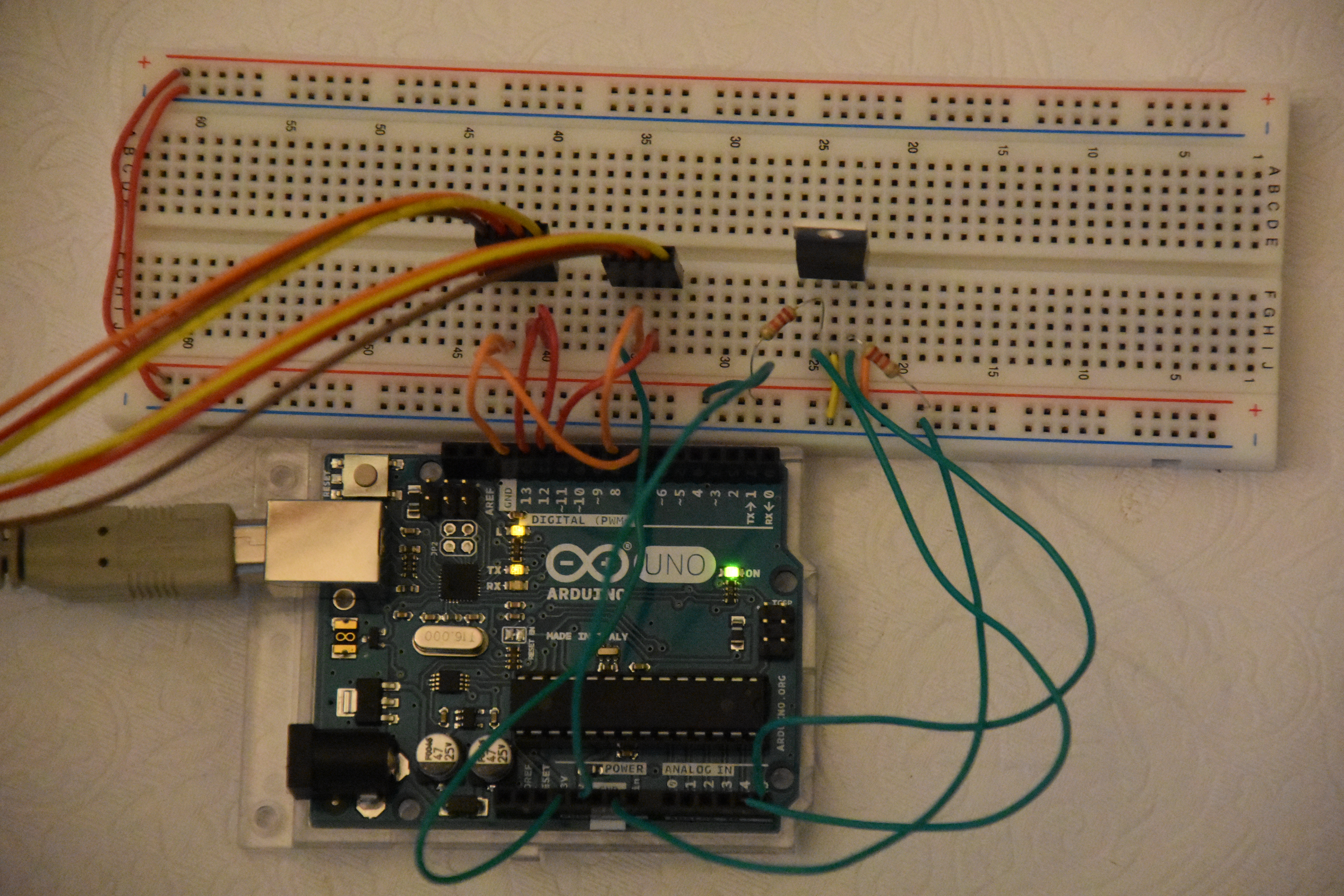 |
| ASCII Data Transmission Prototype | Transmission Circuit |
|---|---|
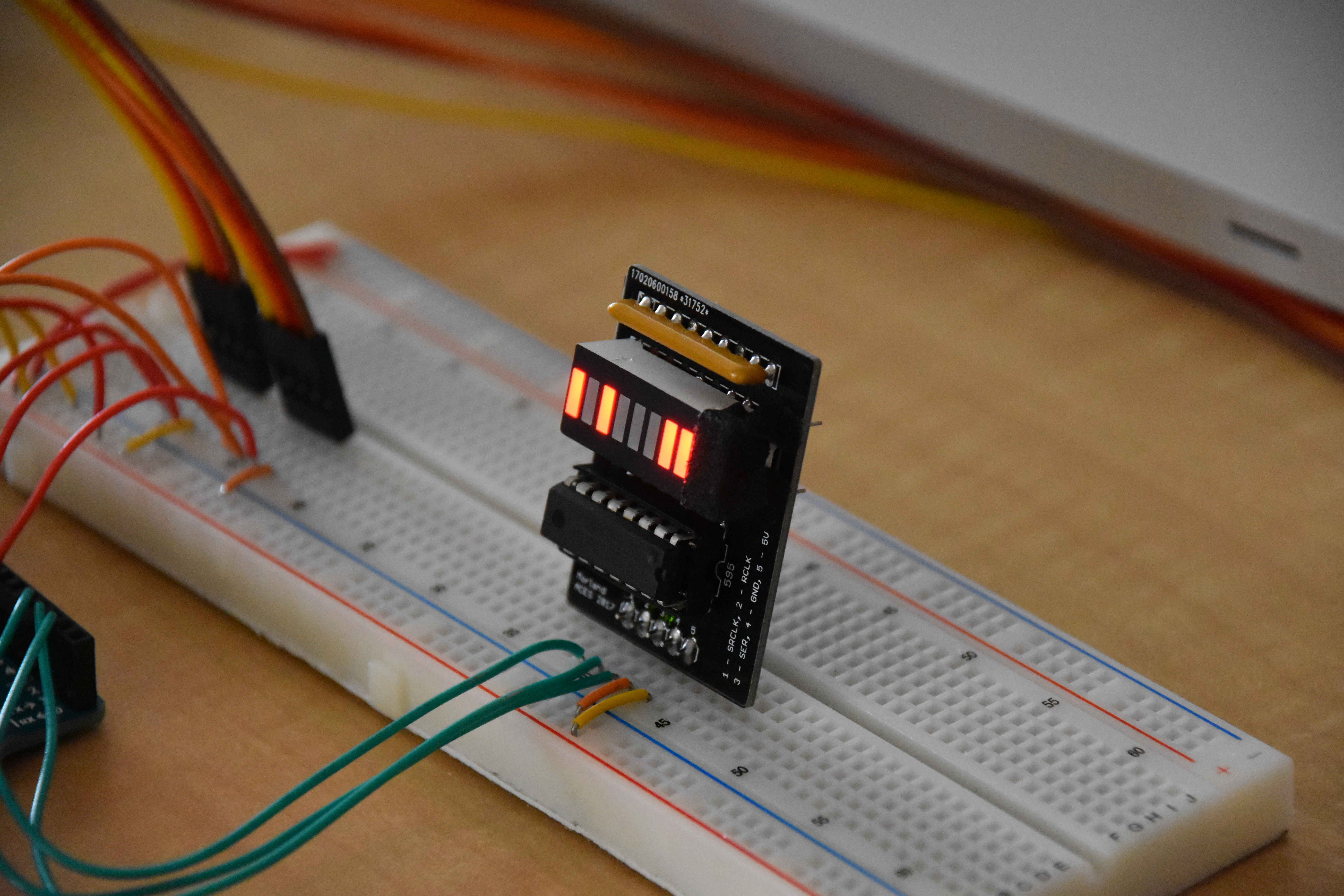
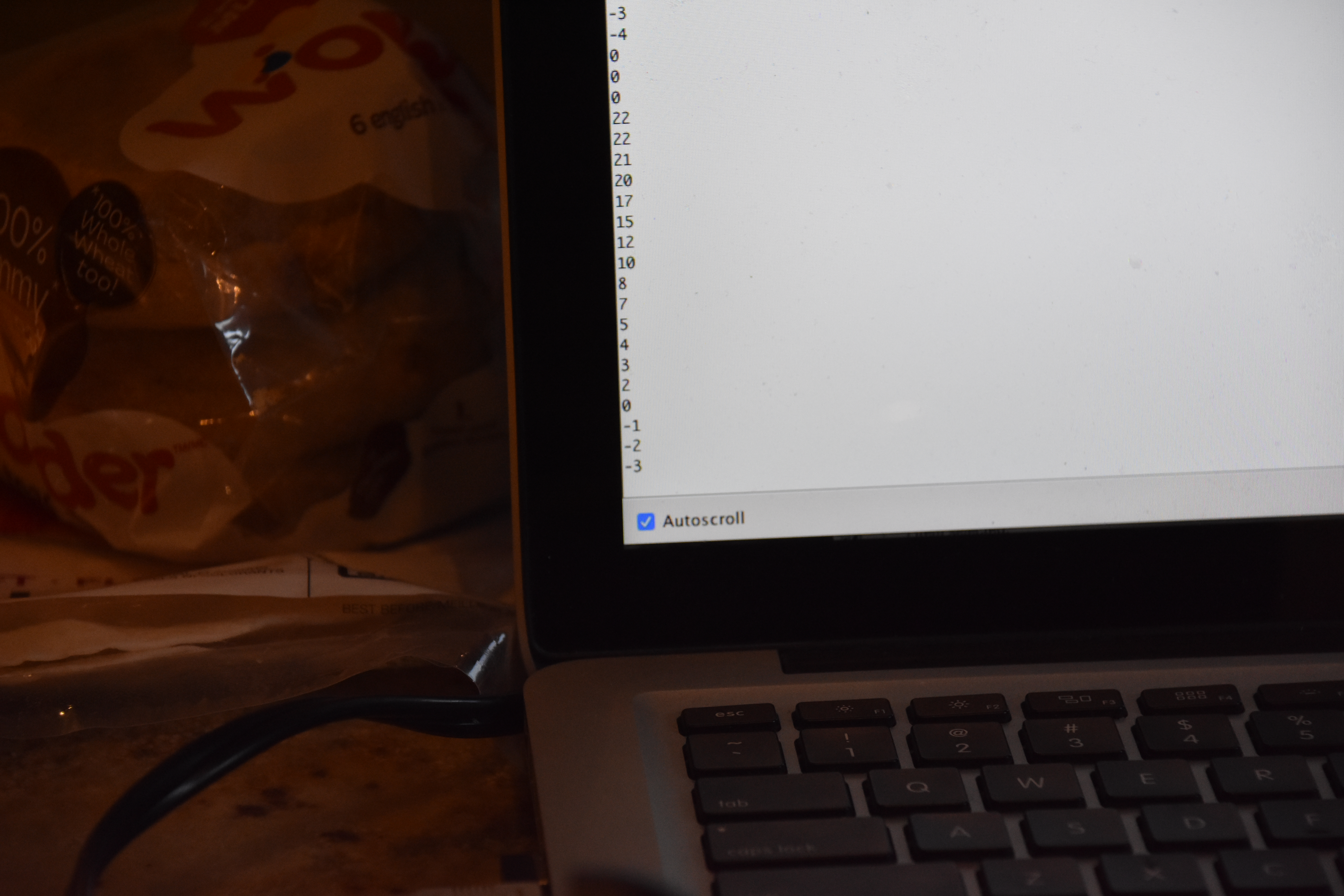 | 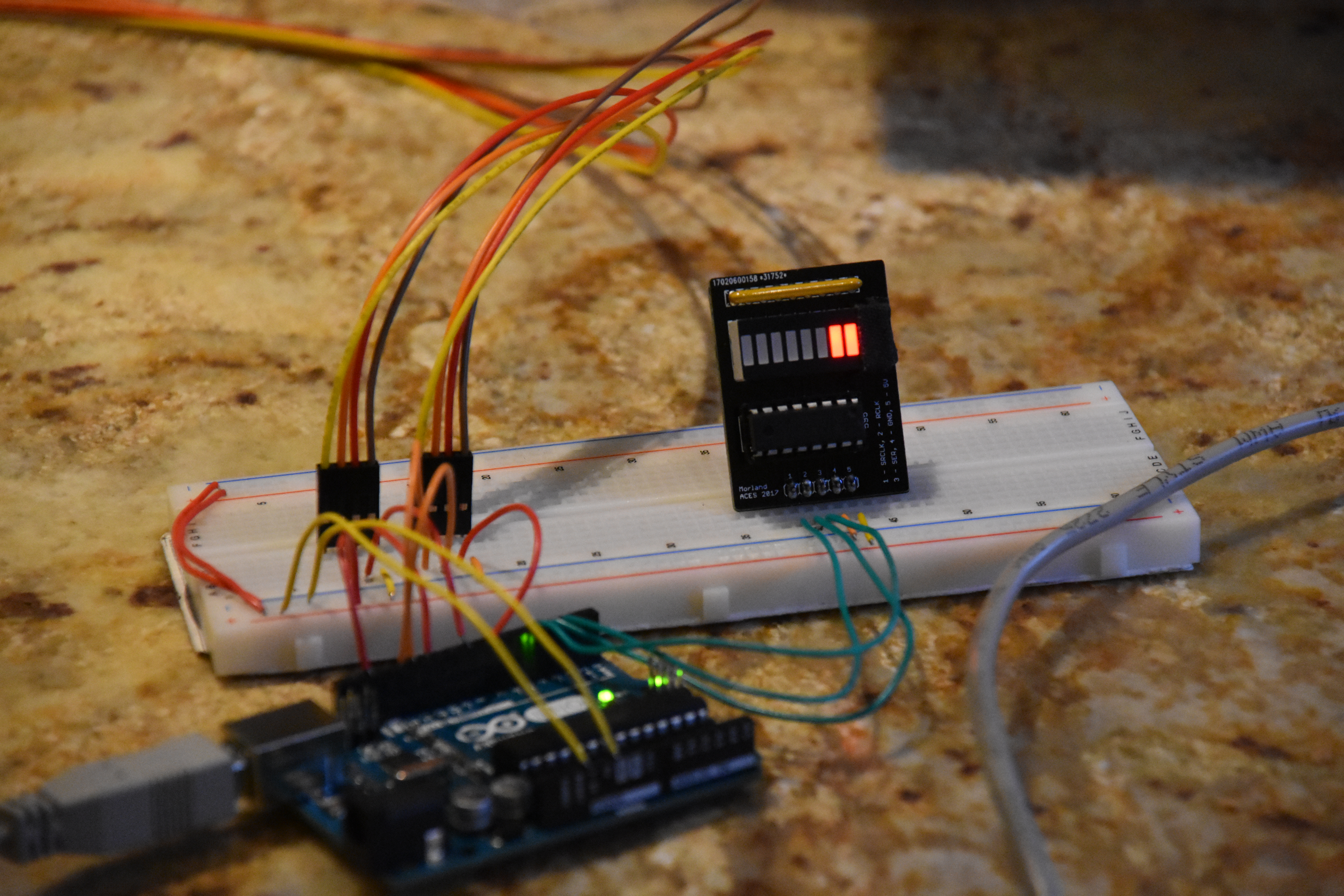 |
| Reading the current temperature on the receiver serial monitor | Bar graph representation of the current temperature |
| Link to YouTube Video: https://youtu.be/gddaoh8Qxrs | |
Code
Transmitter Code
//UNO TRANSMITTER CODE
#include <nRF24L01.h>
#include <RF24.h>
#include <RF24_config.h>
#include <printf.h>
#include <Wire.h>
#define CHANNEL 106
#define TEMPSENSORADDRESS 72
int8_t currentTemp;
RF24 radio(7, 8);
byte addresses[][6] = {"1Node", "2Node"};
void setup() {
// initialize libraries
radio.begin();
Serial.begin(9600);
Wire.begin();
//turn off the ADC to conserve power
ACSR = B10000000;
ADCSRA = ADCSRA & B01111111;
DIDR0 = DIDR0 | B00111111;
// set radio settings
radio.setPALevel(RF24_PA_LOW);
radio.setChannel(CHANNEL);
// select addresses to read and write from
radio.openWritingPipe(addresses[0]);
radio.openReadingPipe(1, addresses[1]);
}
void loop() {
currentTemp = readTemp();
radio.write(¤tTemp, sizeof(int8_t));
powerSave(7); // enter low power mode for 7 seconds
}
void powerSave(uint32_t powerOffPeriod) {
radio.powerDown();
delay(powerOffPeriod * 1000);
radio.powerUp();
delay(6); // delay as radio boots
}
int8_t readTemp() {
// prepare wire library to read from temperature sensor
Wire.beginTransmission(TEMPSENSORADDRESS);
Wire.write(0);
Wire.endTransmission();
// read temperature from sensor
Wire.requestFrom(TEMPSENSORADDRESS, 1);
while (!Wire.available());
return Wire.read();
}
Receiver Code
//UNO RECEIVER CODE
#include <nRF24L01.h>
#include <RF24.h>
#include <RF24_config.h>
#include <printf.h>
#include <EEPROM.h>

#define CHANNEL 106

#define DATAPIN 4
#define LATCHPIN 3
#define CLKPIN 2

int8_t receivedData;
uint8_t eepromAddress;

RF24 radio(7, 8);
uint8_t wirelessAddresses[][6] = {"1Node", "2Node"};

void setup() {

  // initalize shift register pins
  pinMode(DATAPIN, OUTPUT);
  pinMode(LATCHPIN, OUTPUT);
  pinMode(CLKPIN, OUTPUT);


  // initialize libraries
 Serial.begin(9600);
  radio.begin();

  // set radio settings
  radio.setPALevel(RF24_PA_LOW);
  radio.setChannel(CHANNEL);

  // select addresses to read and write from
  radio.openWritingPipe(wirelessAddresses[1]);
  radio.openReadingPipe(1, wirelessAddresses[0]);
  radio.startListening();

}

void loop() {

  // whenever a tempature is available
  // place into eeprom and display it on bargraph

  if (radio.available()) {

    radio.read(&receivedData, 1);

    Serial.println(receivedData);

    if (eepromAddress == EEPROM.length()) eepromAddress = 0;
    EEPROM.write(eepromAddress, receivedData);
    eepromAddress++;

    displayTemp(map(receivedData, -20, 80, 0, 8));

  }
}

void displayTemp (uint8_t data) {

  uint8_t shiftData = 0;

  for (uint8_t n = 0; n < data; n ++) shiftData |= (1 << n);

  shiftOut(DATAPIN, CLKPIN, LSBFIRST, shiftData);
  digitalWrite(LATCHPIN, HIGH);
  digitalWrite(LATCHPIN, LOW);
}
Conclusion
In conclusion, this project was a success. While our (Tim Morland and I) original goal was to have the ATTiny85 as a transmitter chip, we found that using the UNO provided more possibilities for data collection. Thus, we are happy with our decision to switch to the UNO. We learned quite a lot about how to use the NRF24L01 wireless chip works and what you can do with it, like shutting it off to use minimal power, for example. We spent hours in the lab and an entire day working on this project, and are satisfied with the final result. We do not believe that any of this time was not worth the final result. I intend to extend my knowledge of the NRF24L01 chip in the future, maybe by incorporating it into an ISP or some other project.
Reference
Logush, Oliver. "Wireless Lesson." ACES, RSGC, http://mail.rsgc.on.ca/~ologush/WirelessLesson.html. Accessed 11 Mar. 2017.
"Optimized High Speed NRF24L01+ Driver Class Documenation: RF24 Class Reference." Optimized High Speed NRF24L01+ Driver Class Documenation: RF24 Class Reference, Github, http://tmrh20.github.io/RF24/classRF24.html. Accessed 11 Mar. 2017.