Short ISP: Nixie Tube Clock
Purpose
The purpose of this project is to create a clock that displays the current time, in a 24h format, on 4 nixie tubes. The clock is to show the accurate time, despite power loss, and have only one power supply.
| Parts List | |
|---|---|
| ATmega328P | 16MHz Crystal Oscillator |
| 2× 22pF Capacitor | 680pF Capacitor |
| 2× 1nF Capacitor | 10nF Capacitor |
| 2.2µF@250V Capacitor | 220µF Capacitor |
| 19× 10KΩ Resistor | 4× 47KΩ Resistor |
| 680KΩ Resistor | 1KΩ Resistor |
| 0.22Ω@2W Resistor | 4.3KΩ Resistor |
| 2.5KΩ Potentiometer | 1N4148 Diode |
| MUR1100 Diode | BC556 PNP Transistor |
| IRF840 N-Channel MOSFET | 150µH@3A Inductor |
| MC34063 Switching Regulator | Chronodot I2C RTC |
| 2× SN74HC595 Shift Register | 4× K155ID1 BCD Converter |
| 4× IN-14 Nixie Tubes | Slide Switch |
| 7805 5V Voltage Regulator | DC Power Jack |
| 9V Power Supply |
Procedure
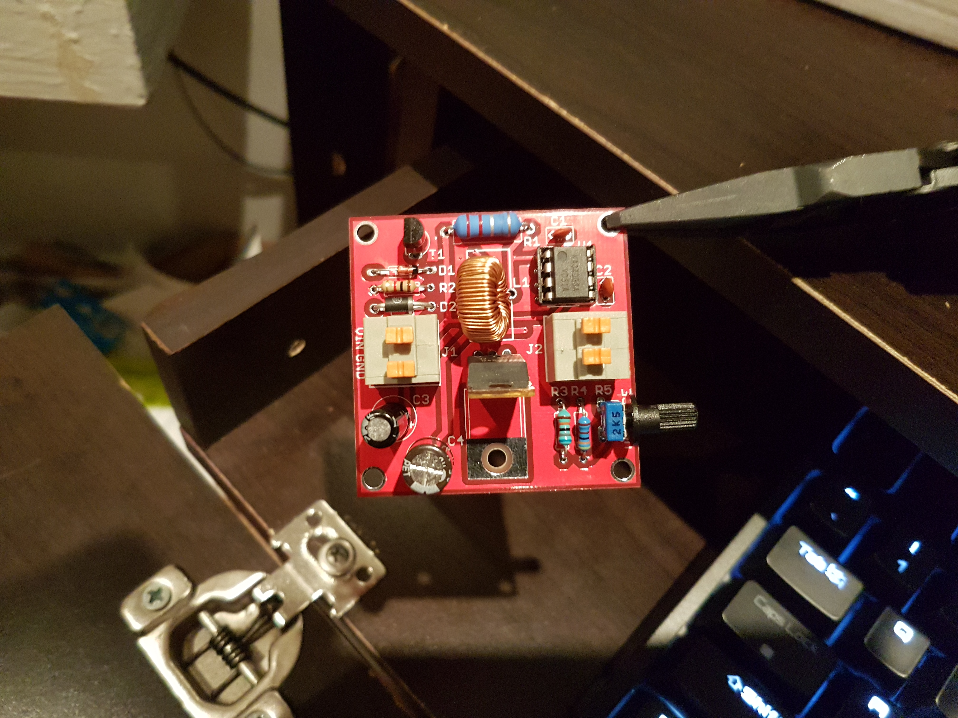
This ISP began as an idea while completing the 555 Boost converter circuit. Next, the idea developed a true project with the purchase of nixie tubes and BCD chips on eBay. The creation of a possible schematic occurred as the parts were in the mail. The schematic in question contained a boost converter circuit as well as the nixie tube and driver circuitry. The boost converter in the original circuit was not successful as the capacitors inside the MOSFET interfered with the PWM signal of the ATmega328P and fried it. Next was building a 555 boost converter, which increased voltage to desired levels, but could not sustain load. Instead, an eBay boost converter specifically designed for nixie tubes was purchased.
Code writing started as soon as the nixie tubes and BCD chips arrived. The programming of the chronodot started the adventure into coding a clock. First, the code calls the hex data for the current hour minute and second from the chronodot using the Wire.read() function.
The readTime function formats this data into a human-readable decimal value. Next, the decimal values get fed into the timeData function. This function takes the decimal values and, using the toNibble function, creates a 16 digit long string of 1s and 0s. Each digit in the string represents an output on the shift register and each group of 4 digits, or binary nibble, represents a digit on the clock. The toNibble function takes the binary value of a digit and creates a string exactly 4 digits long.
After formatting the current time in a way that the shift registers and BCD chips can read, the shiftTime function sends this data out. The shiftTime function runs through an entire string and sends the corresponding data to the shift registers.
Shift registers use 3 pins to receive information from a device like the ATMega 328P. These pins are the serial data, serial clock and latch pins. The shift register indexes a "1" in its memory when the serial data pin is high and, after that, the serial clock pin is high. If the serial data pin is low and the serial clock pin has been set to high, the shift register indexes a "0". Finally, after receiving all the desired data, the latch pin is set high and the outputs of the shift register change to reflect the data received. The shiftTime function reads the string of 1s and 0s representing the current time and sends this data to the shift registers.
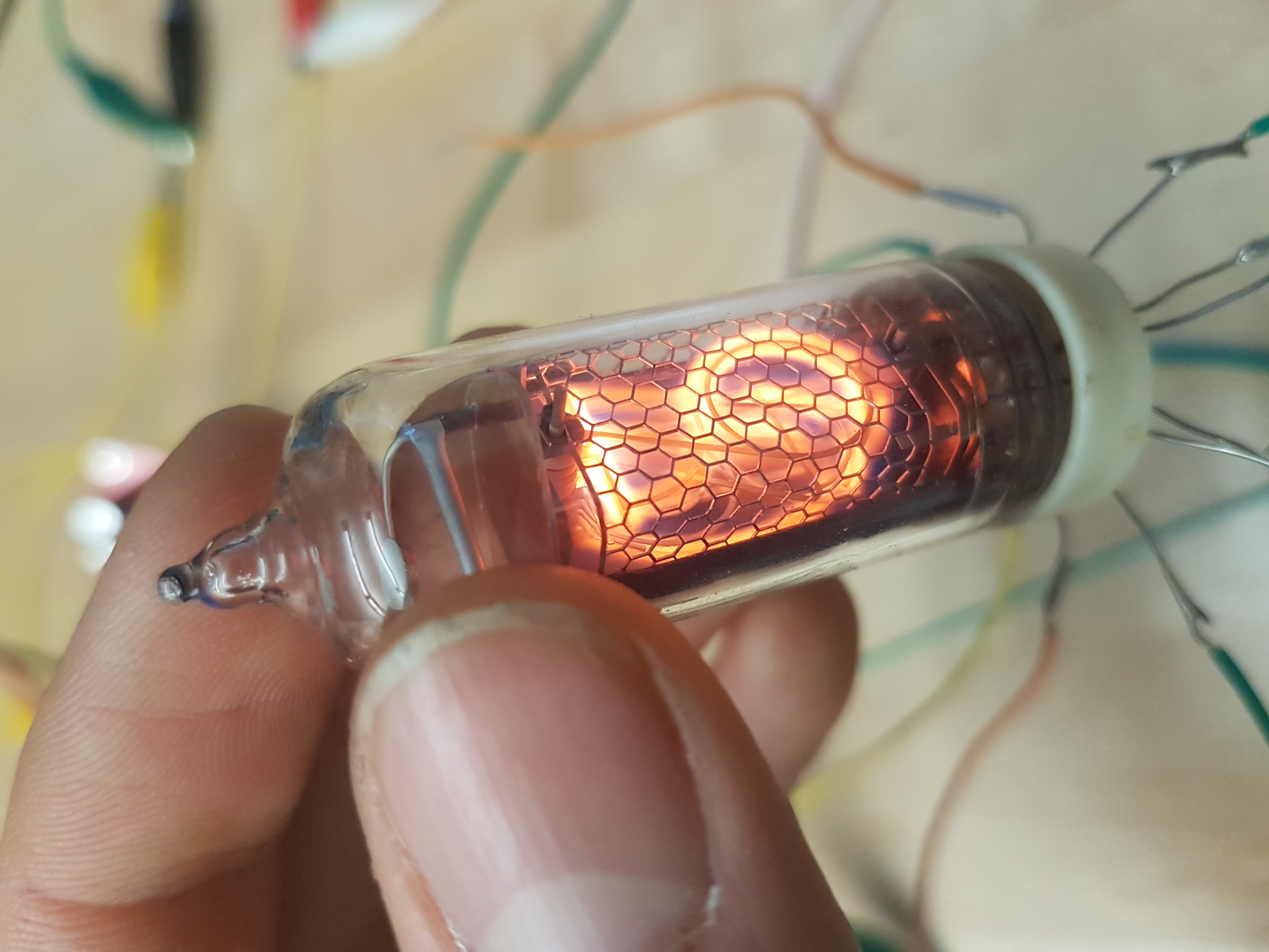
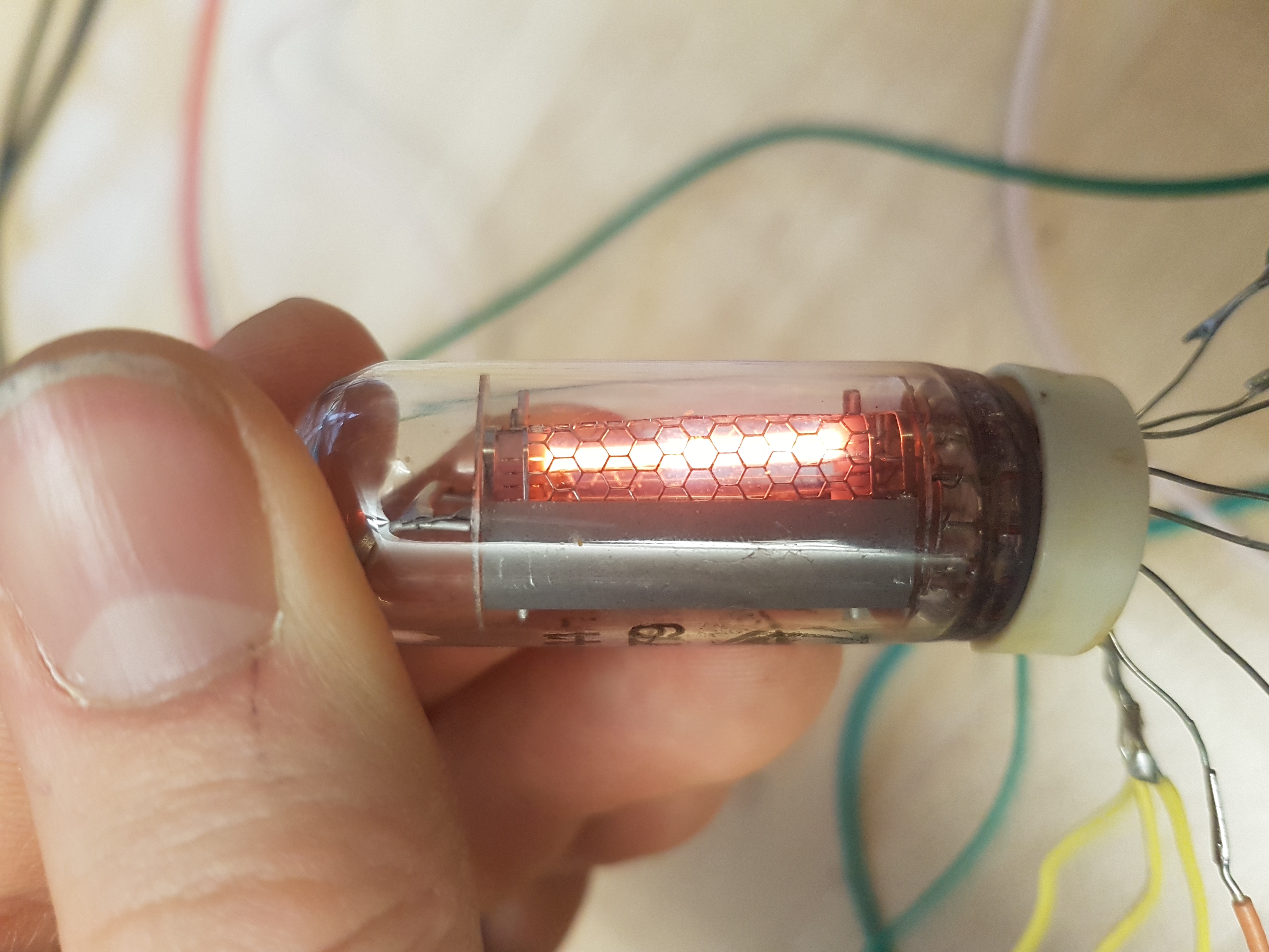
These shift registers connect to К155ИД1 (K155ID1) binary to decimal converter chips. These chips take the binary nibble and ground the appropriate output pins. The pins ground incoming current because they are specially designed for ИН-14 (IN-14) nixie tubes, which have a common anode.
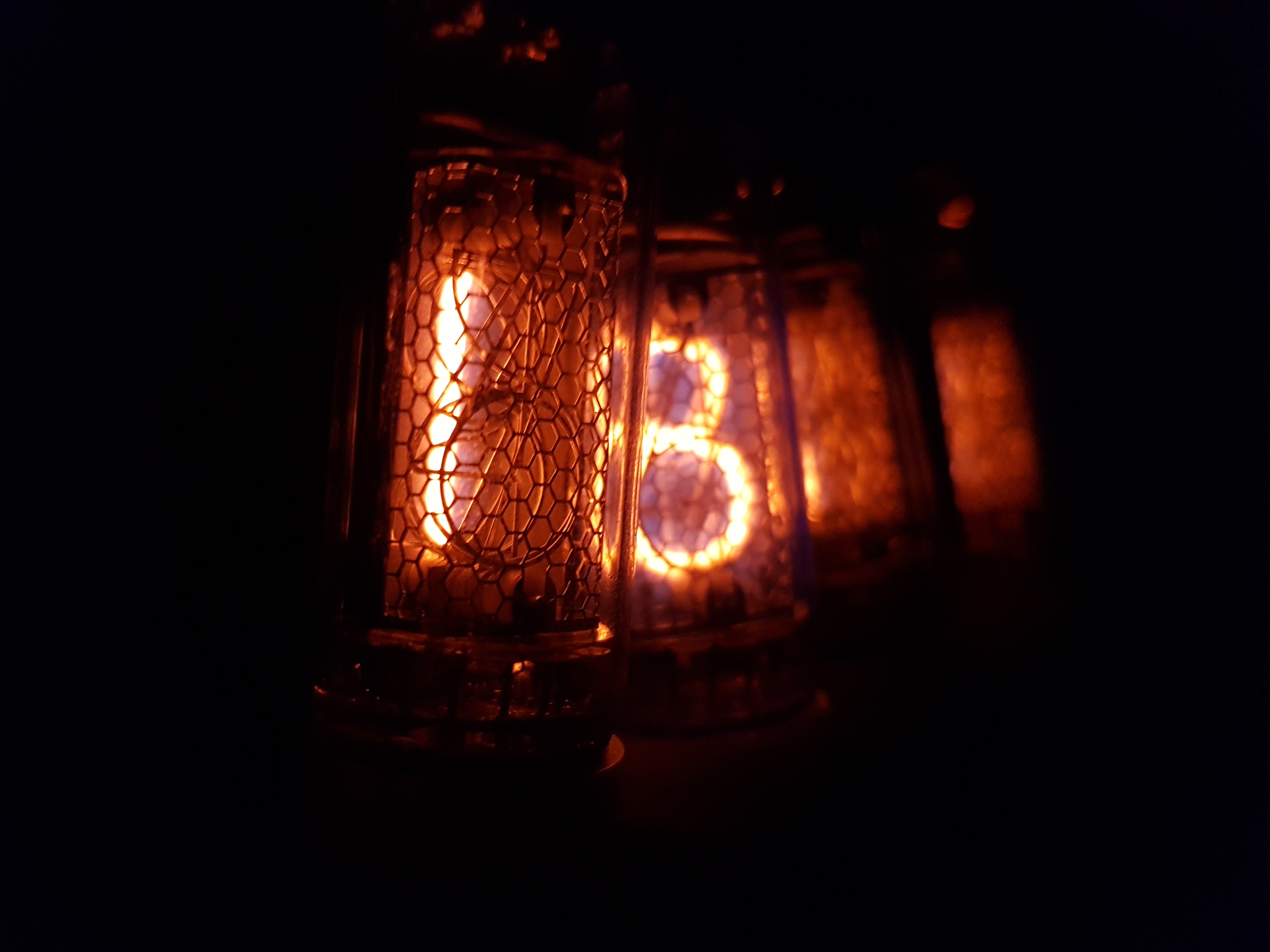
Nixie tubes work by lighting a filament inside a glass chamber filled with gas. This gas often consists of neon and some mercury or argon. They need 150V-170V to run and can run off AC or DC. The digits are completely separate from each other and, as such, multiple digits can appear concurrently as in the picture to the right. These specific tubes were manufactured in the USSR and used as numerical displays before the invention of the 7 segment layout.
The final additions to the code were a daylight savings time switch and the cycleTubes function. The DST switch allows for a user to efficiently move the hour forward and back on demand. The cycleTubes function gets called every hour, on the hour, to prevent cathode poisoning on the nixie tubes. Cathode poisoning occurs when a digit is on for a prolonged period of time. The coating on this digit sprays onto nearby digits resulting in dimmer patches and less clear numbers. Cycling through all the possible displays once an hour, prevents this.
The final addition was the boost converter to power the nixies. Each tube was individually tested for operation and connected to the circuit. A 47KΩ resistor placed on the anodes of each tube to prevents high current from frying the BCD chips. The addition of a 5V voltage regulator allowed the logical components and the nixies to share the same singular power source. The clock was now complete.
Media
 |  |
| Demonstrating the layering of digits on a Nixie Tube. "6" is illuminated here. | 130V-170V DC Boost Converter Circuit |
|---|---|
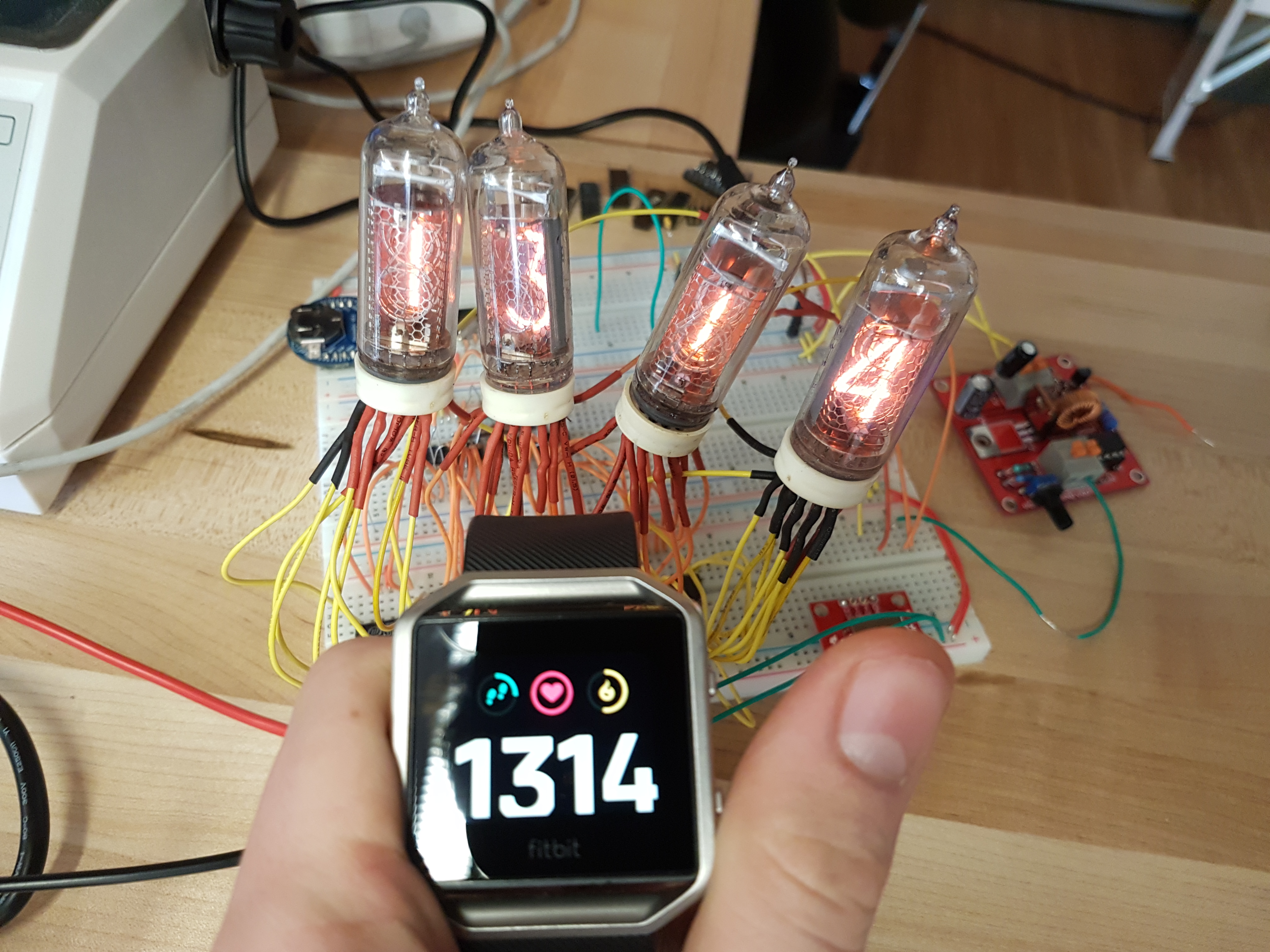 |  |
| Accurate time displaying on the clock | Nixie tubes at night |
| Link to YouTube Video: https://youtu.be/ri43Dtk1gDY | |
Code
Main Clock Code
//Name: Ethan McAuliffe
//Date: 2016-12-17
//Project: Nixie Tube Clock
//Status: Functional and Tested

//Libraries
#include <Wire.h>

//Constants
#define serial 2
#define latch 3
#define clk 4
#define DSTPin 9
#define rtc 0x68

//Variables
String currentTime; // current time formatted for the shift registers
int8_t daylight; //daylight savings offset
uint8_t cHour; //current hour
uint8_t cMinute; //current minute
uint8_t cSecond;  //current second

void setup() {
  Wire.begin();

  pinMode(serial, OUTPUT);
  pinMode(latch, OUTPUT);
  pinMode(clk, OUTPUT);

  pinMode(DSTPin, INPUT_PULLUP);
}

void loop() {
  //Interface with the RTC
  Wire.beginTransmission(rtc);
  Wire.write(0); //prepare rtc to be read from
  Wire.endTransmission();
  Wire.requestFrom(rtc, 7);
  while (Wire.available() == 0);
  //read current  minute and hour
  cSecond = readTime(Wire.read());//second
  cMinute = readTime(Wire.read() & 0x7f); //minute
  cHour = readTime(Wire.read() & 0x3f); //hour

  //if the daylight savings time switch is on, add add 1 hour to the current time
  digitalRead(DSTPin) == LOW ? (cHour == 23 ? daylight = -23 : daylight = 1) : daylight = 0;

  //takes current time and sends it to the shift registers
  currentTime = timeData(cHour + daylight, cMinute); // current time binary data. Each nibble represents a digit.
  shiftTime(serial, latch, clk, currentTime); //send current time to the shift registers

  //cycles nixie tubes every hour that they are on
  if (cMinute == 0 && cSecond == 0) {
    cycleTubes();
  }
}

//Functions
String timeData(uint8_t h, uint8_t m) { //takes the current time and outputs the required data for shift register
  String minutesOnes = toNibble(String((m % 10), BIN));//converts ones digit to binary nibble
  String minutesTens = toNibble(String((m / 10 % 10), BIN));//converts tens digit to binary nibble
  String hoursOnes = toNibble(String((h % 10), BIN));
  String hoursTens = toNibble(String((h / 10 % 10), BIN));

  //output a string of the all binary nibbles for each digit in the time
  String output = hoursTens + hoursOnes + minutesTens + minutesOnes;
  return output;
}

String toNibble (String input) { //converts binary character string to a binary nibble
  String output = input;
  uint8_t lngth = output.length();
  for (uint8_t i = lngth; i < 4; i++) { //adds zeros before binary value until there is a whole nibble
    output = "0" + output;
  }
  return output;
}

void shiftTime (uint8_t serialPin, uint8_t latchPin, uint8_t clockPin, String inputTime) { //sends a binary string to shift registers
  digitalWrite(latchPin, LOW);//set latch pin low to prepare for data to be sent
  for (int8_t i = inputTime.length() - 1; i > -1; i--) { //iterates over entire length of input string
    byte currentChar = inputTime.charAt(i);//gets character "i" in the binary string
    if (currentChar == '1') { //if character is a one send a high signal to the shift registers
      digitalWrite(serialPin, HIGH);
      digitalWrite(clockPin, HIGH);
      digitalWrite(clockPin, LOW);
      digitalWrite(serialPin, LOW);
    } else { //if character is a zero send a low signal
      digitalWrite(serialPin, LOW);
      digitalWrite(clockPin, HIGH);
      digitalWrite(clockPin, LOW);
    }
  }
  digitalWrite(latchPin, HIGH);//lock in data on shift register
}

void cycleTubes () {//cycle all of the digits in unison to prevent cathode poisioning
  for (uint16_t i = 0; i < 1000; i++) {
    uint8_t cycleDigits = ((i % 10) * 10) + i % 10;
    String cycleData = timeData(cycleDigits, cycleDigits);
    shiftTime(serial, latch, clk, cycleData);
    delay(i / 15 + 1);
  }
}

uint8_t readTime (uint8_t input) { //makes time human readable (0-60 and 0-24)
  return ((input / 16 * 10) + (input % 16));
}
Conclusion
In conclusion, I found this project to be quite enjoyable and informative. I enjoyed working with even higher voltages than my previous project, despite being shocked more than a few times. It was fun to learn how to use niche devices to create a device that we use multiple times a day. I also learned some electronic history by reading up on nixie tubes and why they were used. I fully intend to extend this project further and create a custom circuit board using EAGLE as well as designing an enclosure using ViaCAD. I also intend to finally decode the mystery of boost converters (although I believe I know where I went wrong). I put an immense amount of time into this project, but I do not believe that any of it was wasted. I am very much satisfied with my final product.
Reference
Alberto. "ATMEGA328 & Arduino Pinout Diagram." PighiXXX, 18 Feb. 2013, http://v.gd/miZ3gY.
Boxall, John. "Using DS1307 and DS3231 Real-Time Clock Modules with Arduino." Tronixstuff, Tronixlabs, 1 Dec. 2014, http://tronixstuff.com/2014/12/01/tutorial-using-ds1307-and-ds3231-real-time-clock-modules-with-arduino/.
Harrison, Mike. "Nixie Power Supply." Mike's Electric Stuff, http://www.electricstuff.co.uk/nixpsu.html.
"IN-14 (ИН-14) Datasheet." TubeHobby, Gazotron, http://tubehobby.com/datasheets/in14.pdf.
"K155ID1 (К155ИД1) Datasheet." TubeHobby, CCCP, http://tubehobby.com/datasheets/k155id1.pdf.
Onno. "Neon Nostalgia." Neon Nostalgia, 20 Oct. 2000, http://www.glowbug.nl/neon/index.html.
Urbach, Claus-Dieter. "FAQ Nixietubes." NixieClocks.de, http://www.nixieclocks.de/FAQ_Nixietubes.pdf.