555 Project: Boost Converter
Purpose
The purpose of this challenge was to create a circuit that incorporated the 555 timer IC in some way. The purpose of the circuit outlined in this report is to take an input voltage and increase it to a desired output voltage. This is called a "boost converter". The design is intended for a maximum output of ~50V DC. A boost converter with a higher maximum output voltage can be used to drive devices like light bulbs (120V) and nixie tubes(170-200V).
| Parts List | |
|---|---|
| 555 Timer IC | 8 Pin DIP IC Socket |
| 1mF Capacitor | 10pF Capacitor |
| 2× 1KΩ Resistor | 10KΩ Resistor |
| 100µH Inductor | IRF540 N-Channel MOSFET |
| BS170 N-Channel MOSFET | 1N5822 Schottky diode |
| 470µF Capacitor | 1µF Capacitor |
| 33KΩ Potentiometer | 2.2KΩ Resistor |
| ½ size Perma-Proto Breadboard |
Procedure
This challenge started with a search for a 555 timer IC circuit that was both challenging and practical. After much research into switch mode power supplies, the selected circuit was a 555 boost converter.
Following the instructions of a circuit diagram found online, the prototyping stage began. The first step was creating a prototype on a virtual breadboard using Fritzing. This allowed for many redesigns to make it smaller and more efficient.
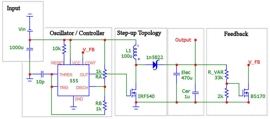
The following step was transferring this design to a real breadboard. First up was wiring the 555 timer IC, in astable mode, using varying sizes of resistors and capacitors to determine the frequency of the output. The output of the 555 connected to the first N-channel MOSFET. The MOSFET, when closed, created a short circuit between the inductor and ground formed.
The high current from a short circuit charged up the electromagnetic field of the inductor. When the MOSFET closed again, the electromagnetic field collapsed into the capacitors. A diode prevented the caps from discharging back into the inductor, forcing them to discharge only through the output wire. Next was wiring a voltage divider, consisting of a potentiometer and a resistor, to the output voltage. This connected to another MOSFET that fed back to the 555 timer IC. Rotating the potentiometer allowed for control over the frequency of the 555 and, by extension, the output voltage.
Finally, the prototype needed testing. The circuit passed; an input of 10v provided an output of more than 30v when under no load. A 100µH inductor replaced the home-made coil, allowing for as much as 50v output, the maximum safe output of the circuit, with a mere 4v input.
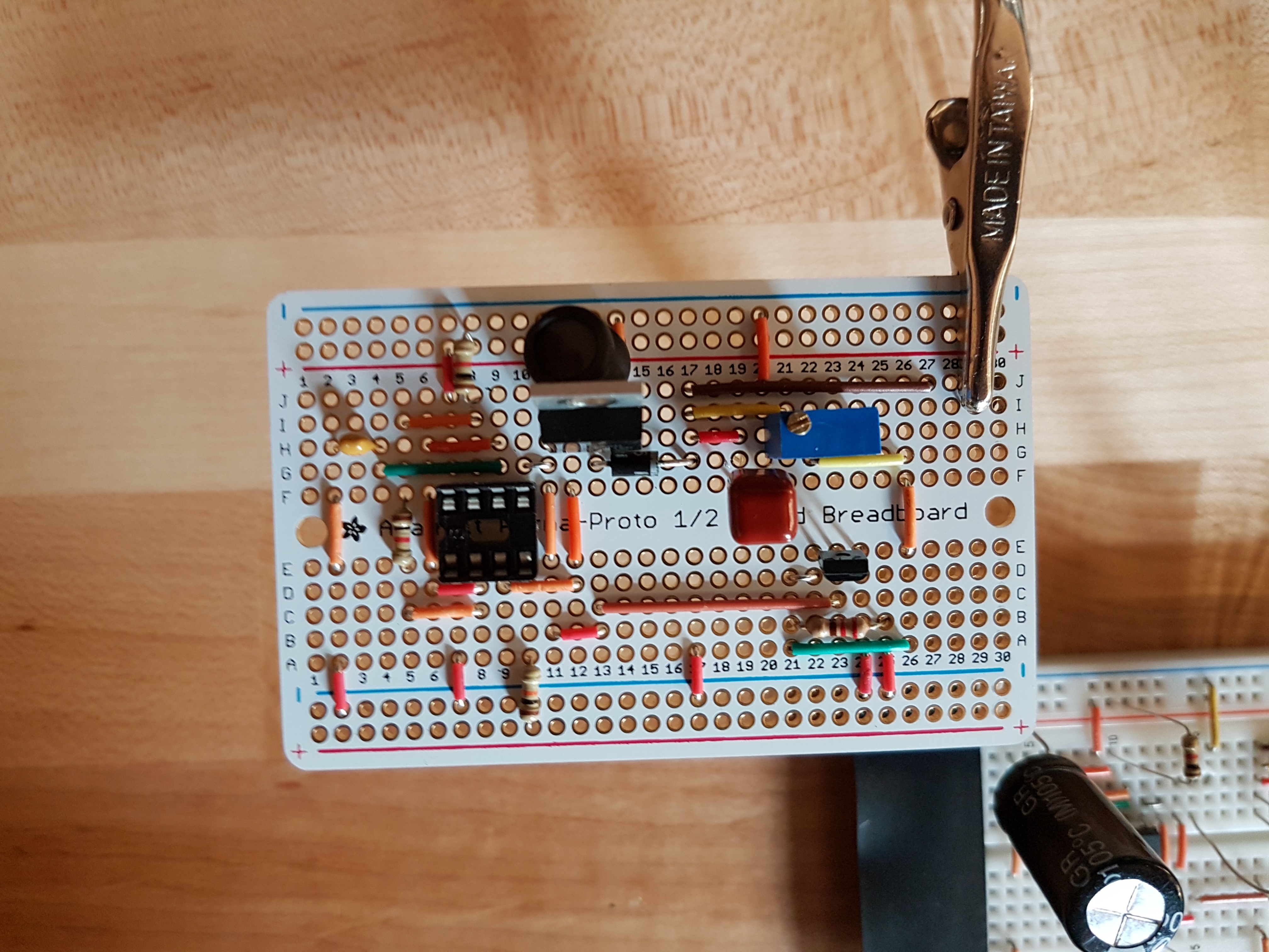
The final step was soldering the circuit to a perma-proto breadboard. This proved to be much more challenging than anticipated. First was completing a dry-fit of the components, as seen partially complete in the picture here. After soldering all of the components to their respective locations on the breadboard, the boost converter was tested again. It failed to work and drew a large amount of current at a low voltage. The solution to this problem was finding the short-circuit and correcting it. Following was another round of testing the circuit. It still did not work correctly. Next was realising the failure, purchasing replacement parts and redesigning the project for a smaller breadboard in Fritzing. After soldering again and testing again, the circuit still did not work. A solution was not found.
Media
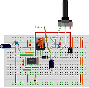 | 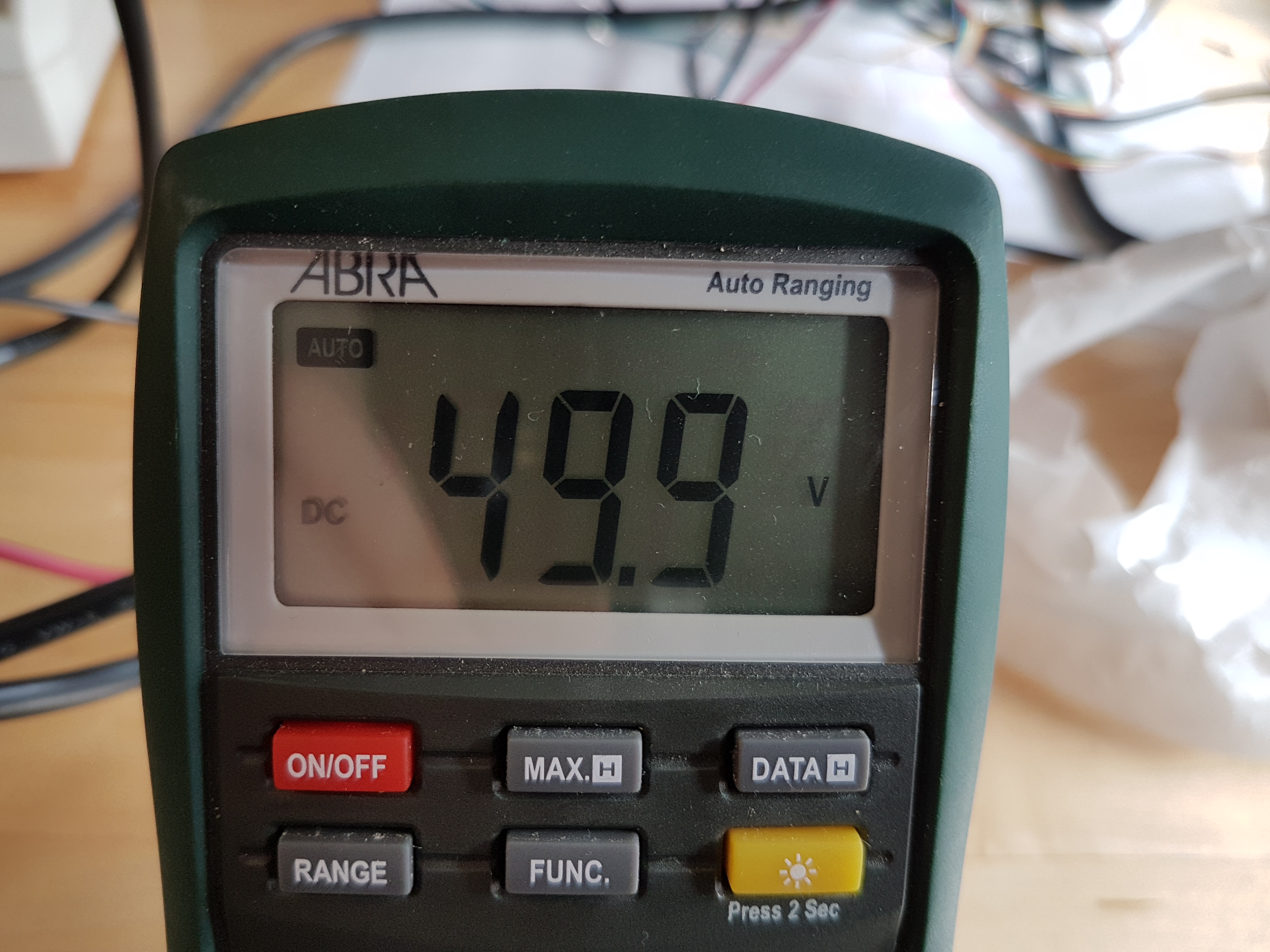 |
| Fritzing Diagram — Prototype #2 | DMM Registering 50 V DC |
|---|---|
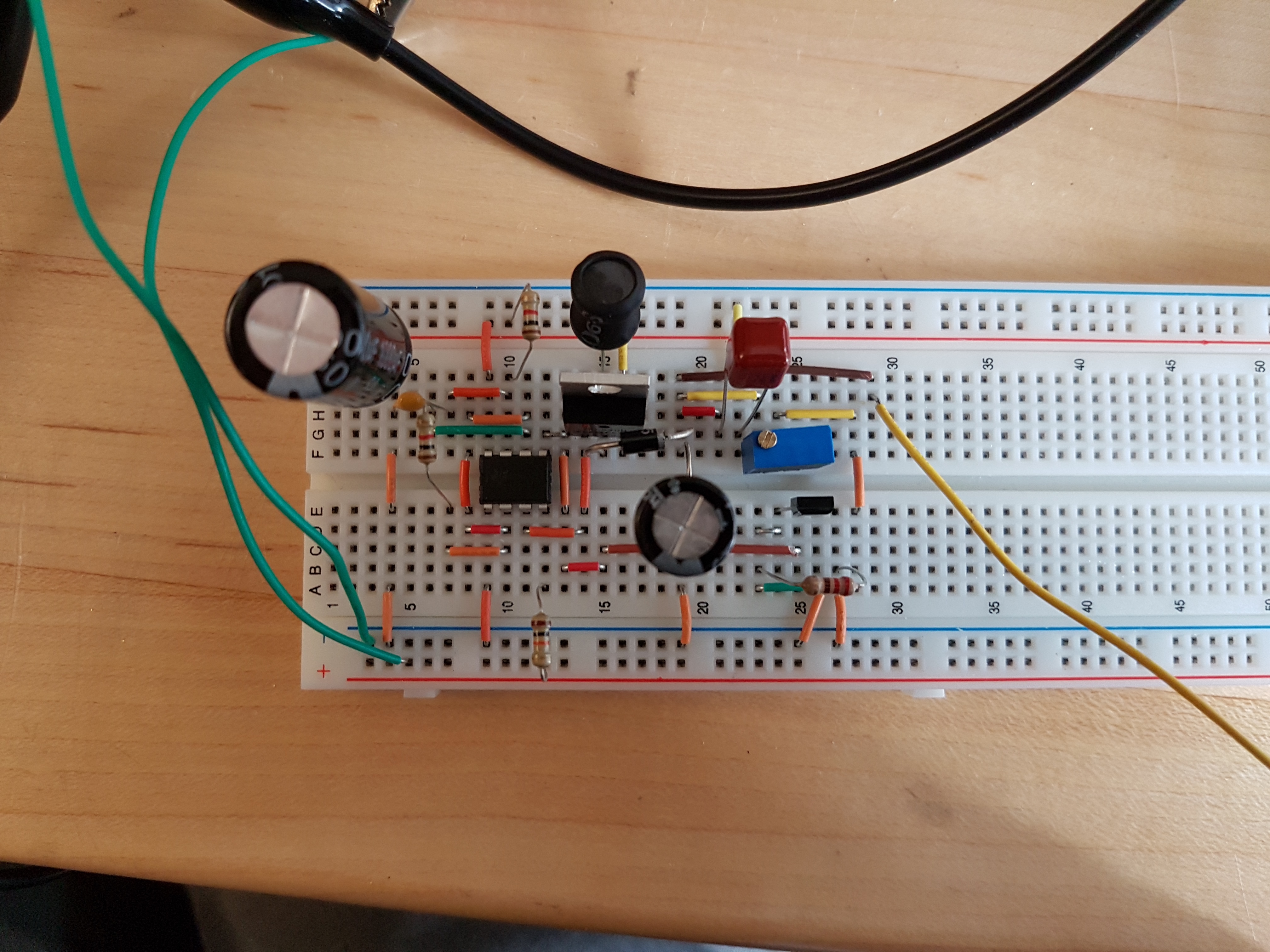 | 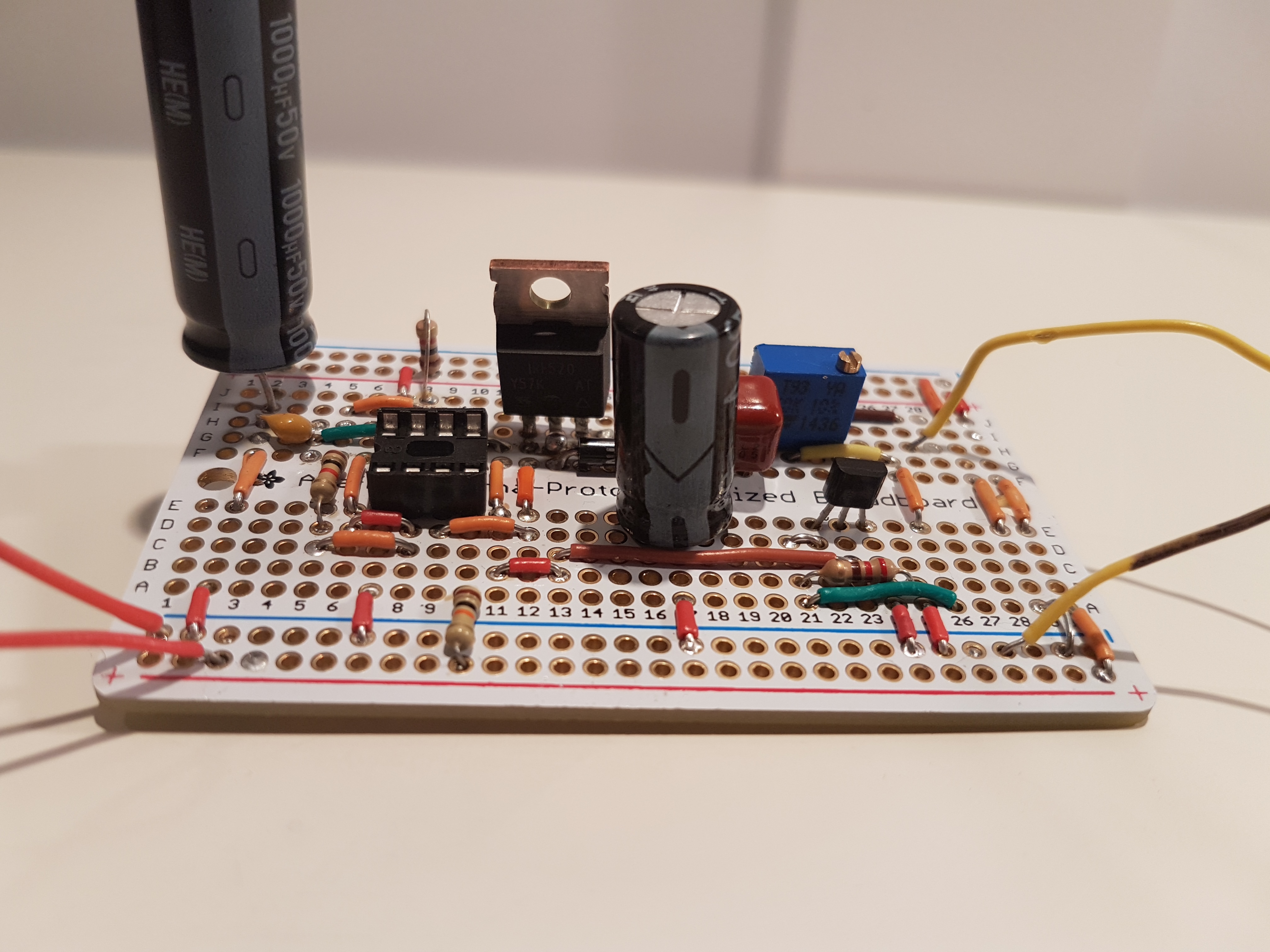 |
| Breadboard Prototype #1 | Soldered Prototype #1 |
| Link to YouTube Video: https://youtu.be/puFw-U7vbZg | |
Conclusion
In conclusion, I found this project to be very fun, but also challenging. I enjoyed working with higher voltages and learning about their applications. Charging up capacitors to 50v and then discharging them to make a loud bang was especially fun. It was satisfying learning how to use the 555 timer IC and the different ways it can be used. I found the soldering part challenging because I could not get the circuit to work properly. I put a lot of time into this project, especially during the troubleshooting stage. While I was unsuccessful in my final result, I feel that this project was entirely worth the effort.
Reference
D'Arcy, Chris. “2016-17 TEI3M Challenges.” RSGC ACES, RSGC, http://darcy.rsgc.on.ca/ACES/TEI3M/1617/Challenges.html#2.
Galanopoulos, Kostas. “555 Boost Converter Circuit.” University of Patras, http://students.ceid.upatras.gr/~galanopu/555_circ.png.
Greatscottlab. “Electronic Basics #12: Coils / Inductors (Part 1).” YouTube, YouTube, 17 May 2015, http://youtube.com/watch?v=kdrP9WbJIb8.