Challenge 1. Analog Sensor
Purpose
The purpose of this circuit is to display the distance an object is from a sensor on a LCD display. The display is to show the distance in cm an object is away from the sensor, a graphical representation of this distance, and the raw analog voltage of the sensor.
| Parts List | |
|---|---|
| Arduino Uno | GP2Y0A41SK0F Infra-Red Distance Sensor with Analog Output |
| 10KΩ Potentiometer | 1447-ADA Standard White on Blue LCD 16x2 |
| USB Type A to Type B Cable |
Procedure
This challenge began with reading the datasheet and the explanation on the ACES website to understand what was going on in the video provided, and how to replicate it. The next step was to wire up the LCD display to the Arduino and connecting the IR sensor for the code to run on. After that, the circuit portion was complete and the code section began.
The code section began with importing the LCD library and configuring the required custom characters. The program needed eight custom characters of different sized rectangles. The next step was the creation of an array to store the hexadecimal values of these rectangle characters. After that was the creation of the desired variables for the program. These included the length of the array of custom characters, the input analog voltage, the distance in cm the object is away from the sensor and the amount of rectangles to display on the LCD.
Following that, the writing of the clearScreen function commenced. It used three inputs, column, row and number of cells, to create a for loop that changed the desired characters to a blank "space" character. The next activity was to configure the LCD panel. The panel needed importing, the custom characters needed creating and the configuring of the constant text needed completing. Completing these tasks required the use of the lcd.begin function to import the display, the custom character creation for loop discussed in class and manually setting the position of the constant text in the setup function. Completing the continuously running code was the next step. The iRead variable created earlier stored the reading of the analog voltage from pin A0 on the Arduino. The map function converted this reading to the distance, which was, in cm, the distance the object was away from the sensor. The disp variable divided this map function in 4 to determine the amount of rectangles to display on a scale of one to eight. The next step was adding a for loop to progressively show to number of rectangles based on the disp variable. After adding the delay function and the clearScreen functions to remove the variables, the code was finished.
Media
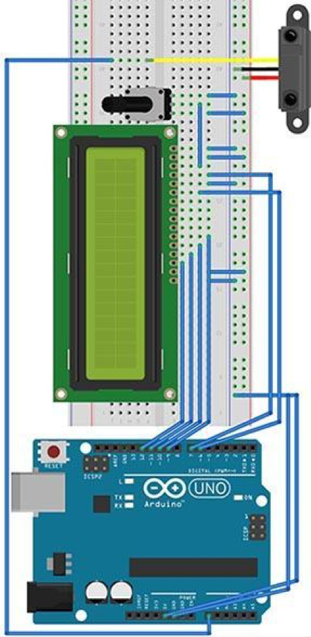 | 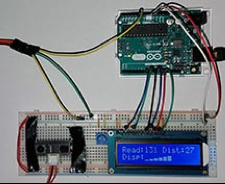 |
| Fritzing Diagram | Picture of the Distance Sensor Circuit |
|---|---|
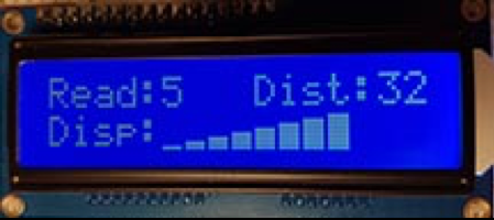 | 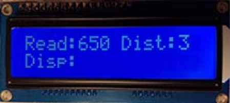 |
| Picture of LCD with no object in front of sensor | Picture of LCD with paper very close to sensor |
| Link to YouTube Video: https://youtu.be/H-DXkPjyVYc | |
Code
//Name: Ethan McAuliffe
//Date: 2016-10-21
//Project: Distance Sensor Challenge
#include <LiquidCrystal.h>

LiquidCrystal lcd(7, 8, 9, 10, 11, 12);

uint8_t customs[] [8] = {
  {
    0x0, 0x0, 0x0, 0x0, 0x0, 0x0, 0x0, 0x1f
  },
  {
    0x0, 0x0, 0x0, 0x0, 0x0, 0x0, 0x1f, 0x1f
  },
  {
    0x0, 0x0, 0x0, 0x0, 0x0, 0x1f, 0x1f, 0x1f
  },
  {
    0x0, 0x0, 0x0, 0x0, 0x1f, 0x1f, 0x1f, 0x1f
  },
  {
    0x0, 0x0, 0x0, 0x1f, 0x1f, 0x1f, 0x1f, 0x1f
  },
  {
    0x0, 0x0, 0x1f, 0x1f, 0x1f, 0x1f, 0x1f, 0x1f
  },
  {
    0x0, 0x1f, 0x1f, 0x1f, 0x1f, 0x1f, 0x1f, 0x1f
  },
  {
    0x1f, 0x1f, 0x1f, 0x1f, 0x1f, 0x1f, 0x1f, 0x1f
  }
};

byte numCustom = sizeof(customs) >> 3;
uint16_t iRead = 0;
byte distance = 0;
byte disp = 0;

void clearScreen(byte col, byte row, byte numCells) { //function to clear requested number of cells in requested position
  lcd.setCursor(col, row);
  for (byte i = 0; i < numCells; i++) {
    lcd.print(" ");
  }
}

void setup() {
  lcd.begin(16, 2);
  for (byte i = 0; i < numCustom; i++) {//creates custom rectangle characters
    lcd.createChar(i + 1, customs[i]);
  }
  lcd.setCursor(0, 0);
  lcd.print("Read:");
  lcd.setCursor(9, 0);
  lcd.print("Dist:");
  lcd.setCursor(0, 1);
  lcd.print("Disp:");
}

void loop() {
  // clear inputs
  clearScreen(5, 0, 4); //clears raw analog data
  clearScreen(14, 0, 2);//clears distance in cm
  clearScreen(5, 1, disp);//clears required distance rectangles

  //read and map inputs
  iRead = analogRead(0);
  distance = map(min(iRead,634), 0, 634, 32, 3);//min function removes input above 3.1V
  //determine the number of bars to be shown
  disp = (distance / 4);

  // output
  lcd.setCursor(5, 0);
  lcd.print(iRead);//print raw analog read
  lcd.setCursor(14, 0);
  lcd.print(distance);//print distance in cm
  lcd.setCursor(5, 1);
  for (byte i = 0; i < disp; i++) {
    lcd.write(i + 1);                //prints distance graph characters
  }
  delay(500);//allows time for a human to read the data on the screen
}
Conclusion
In conclusion, this challenge taught me how to apply the information I learned in class. A large portion of the code that I wrote had already been written in the demonstrations we completed in class. I believe that this project was useful for testing if I was able to comprehend what was being taught in class. I learned how to use the infra-red distance sensor provided to read the distance an object is away in cm. The circuit and code, when configured properly, are successful at completing their purpose.
Reference
D'Arcy, Chris. "RSGC ACES. 2016/17 TEI3M Challenge 1." YouTube. YouTube, 21 Oct. 2016. Web. 22 Oct. 2016. https://www.youtube.com/watch?v=kEHuVYXXAEA.
Fried, Limor. "Character LCDs." Wiring a Character LCD. Adafruit, n.d. Web. 22 Oct. 2016. https://learn.adafruit.com/character-lcds/wiring-a-character-lcd.
"GP2Y0A41SK0F." Sharp World (n.d.): n. pag. Sharp World. Sharp. Web. 22 Oct. 2016. http://www.sharp-world.com/products/device/lineup/data/pdf/datasheet/gp2y0a41sk_e.pdf.