ISP: Digital Logic Gates
Purpose
The purpose of this project is to create a demonstration of logic gates using string, pulleys and weights. The purpose is also to create a breadboard circuit where a logic IC can be swapped out with another to demonstrate how the logic gates work using 7 segment displays.
| Parts List | |
|---|---|
| 21× 2102XB Eyehook | 6× 1 1/2" 4d Nails |
| Clear Shellac Spray | Black Gloss Spray Paint |
| Glossy Clear Coat Spray | Fluorescent Orange Spray Paint |
| 3844cm2 Medium Density Fibreboard | Duct Tape |
| 3× Key Ring | 10× Large Metal Washer |
| Nylon String | "1" Stencil |
| "0" Stencil | 3× Self-leveling Picture Hangers |
| 3× 7-Segment Display | 2× SPDT Switch |
| 6× 470Ω Resistor | 2× 1MΩ Resistor |
| 2× 100Ω Resistor | 3904 NPN Transistor |
| 14 Pin Quad 2-Input Logic Gate IC | 4049 Hex Inverting Buffer |
| 9V Battery or Power Supply | DC Breakout Board |
Procedure
The project began with looking for an idea. The inspiration for the project would eventually come to light late at night surfing the web. The project idea was then submitted to Mr. D'Arcy as an ISP proposal and approved.
Production on the string and weights demonstration of logic gates began first. Next, creation of an outline to base the rest of the project off commenced. When that was complete, purchasing of the necessary supplies followed. Sanding and cutting the medium density fibreboard (MDF) to be perfectly square and smooth was then completed. Measuring the precise position in which to drill holes was the next step. Drilling them was the step after. The size of the holes were slightly increased to allow proper fitting of the eyehooks. Verification of a secure fit between the eyehooks and the holes in the MDF was then accomplished. Painting of the MDF would finally start. It began with three coats of clear shellac to seal the MDF. The application of five coats of high-gloss black spray paint would proceed orange stencilling of "0"s and "1"s. Application of four coats of high gloss clear coat finished the job. The board was then left to dry between each coat for an hour and for 24 hours after the final coat. The 21 eyehooks and six nails were then placed in their respective positions on the board and aligned. Self levelling picture hangers were then positioned and secured to the back of the board. Construction of the logic gates was the next step. Construction started with the NOT and BUFFER gates, then the NAND and AND gates. It then progressed to the OR and NOR gates until finally reaching the XOR and XNOR gates. The XOR and XNOR gates would be prove to be difficult because of the number of weights and connections needed for them to work. Another person would be used to fix this problem. Videos of each gate were then taken and transferred to a computer for safe keeping.
The construction of the logic gate demonstration using 7-segment display was then started. This proved slightly more challenging than originally thought because of current back-flow and the fact that a high signal would be needed to show a "0". The fabrication of the 7 segment display representation began by gathering the required materials (7-segment display, switches, breadboard and power) and placing them in logical positions on the breadboard. Many designs of the circuit were then created. The final design was then chosen for being clean, reliable and straightforward.
The finishing touch of a NOR truth table was then attached to the MDF.
Media
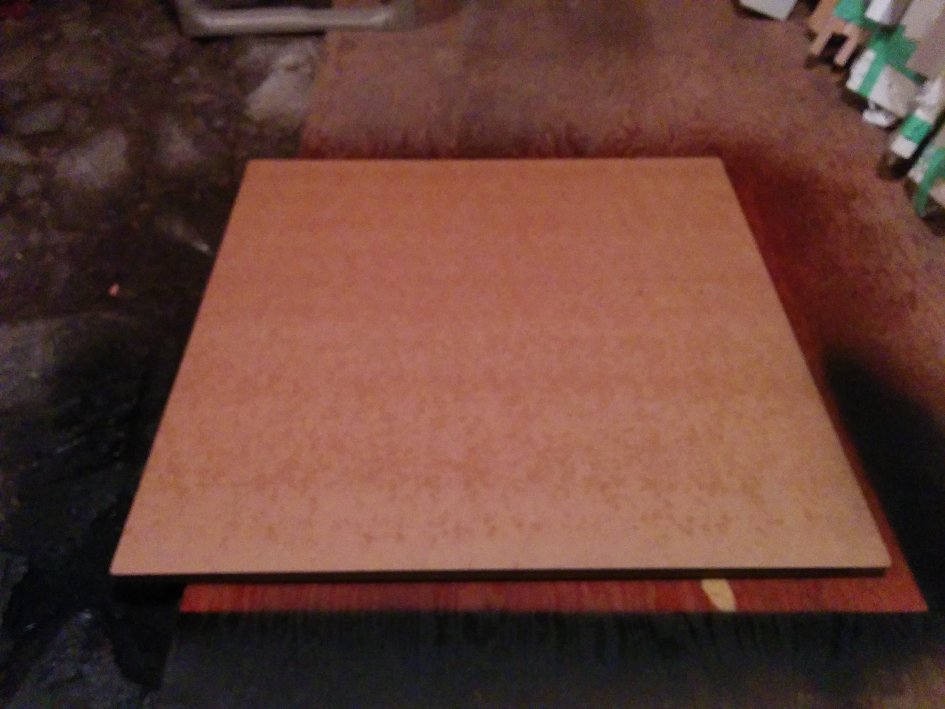 | 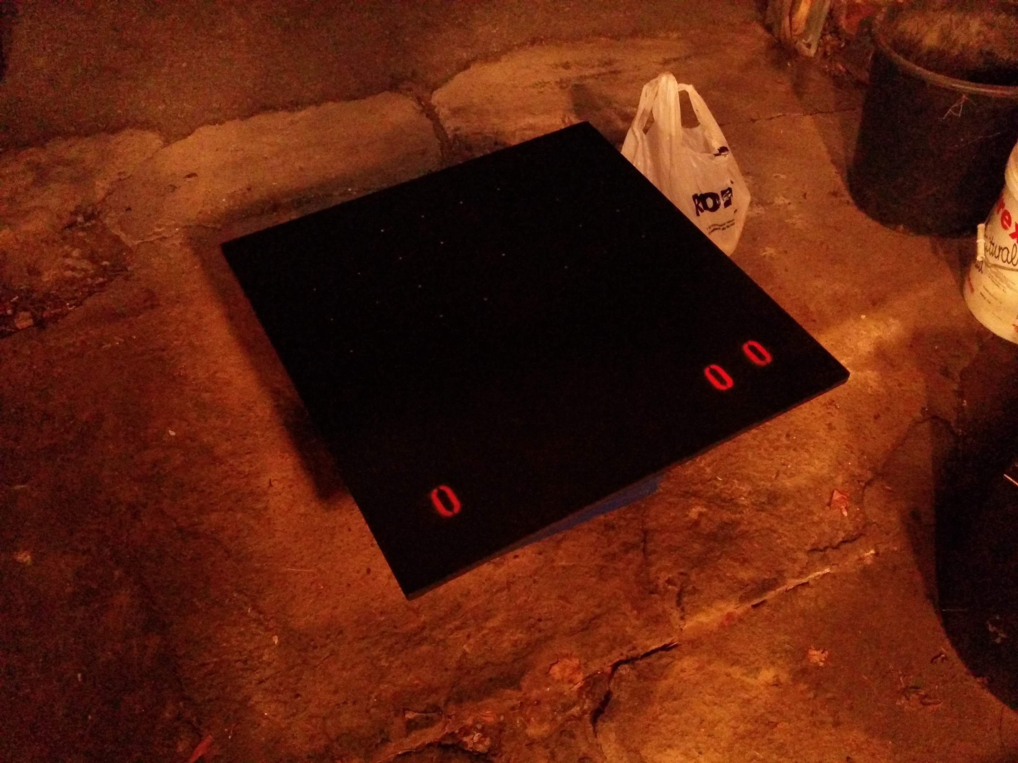 |
| Applying Shellac to the MDF | Stenciling the "0"s on the painted MDF |
|---|---|
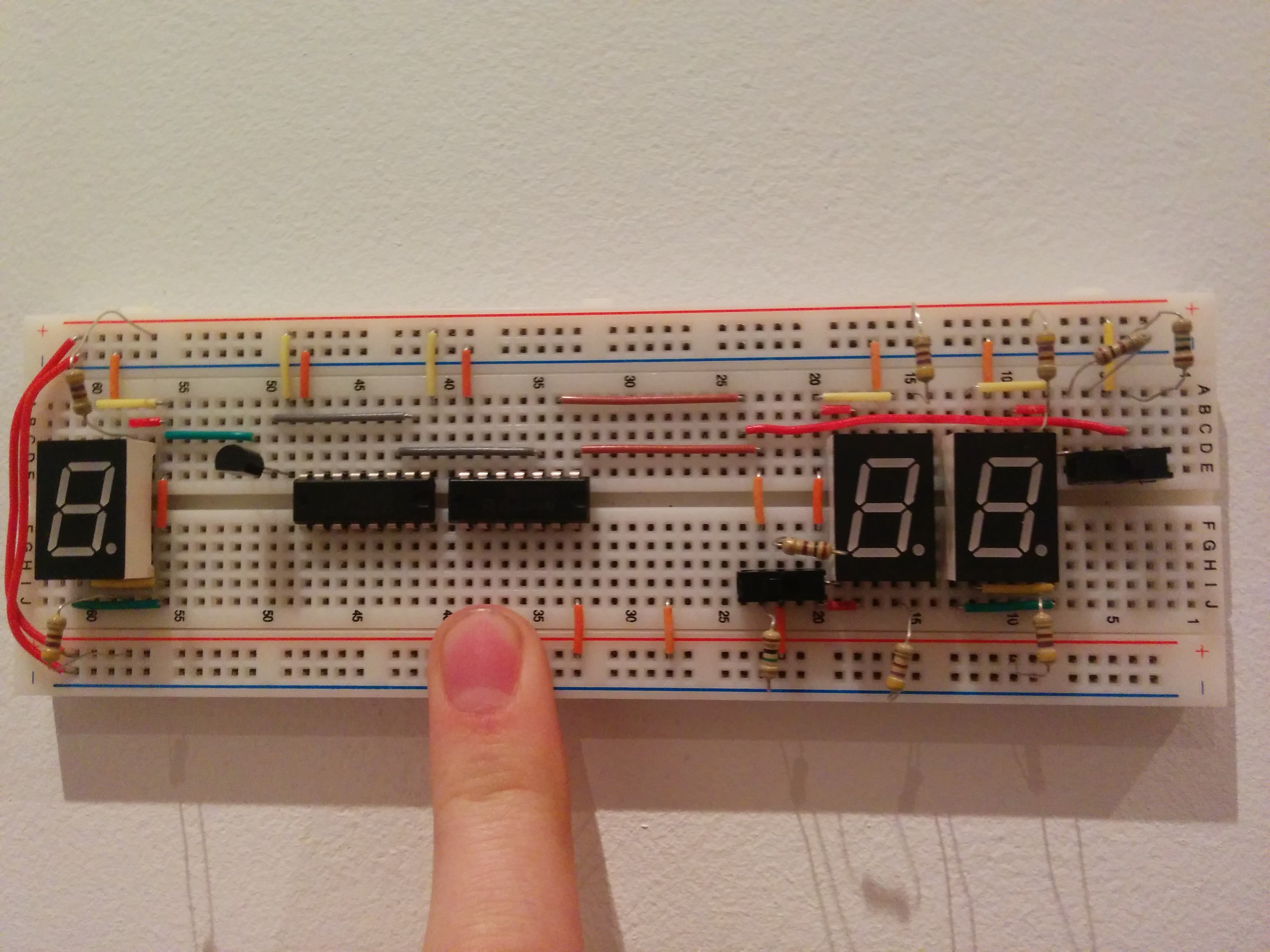 | 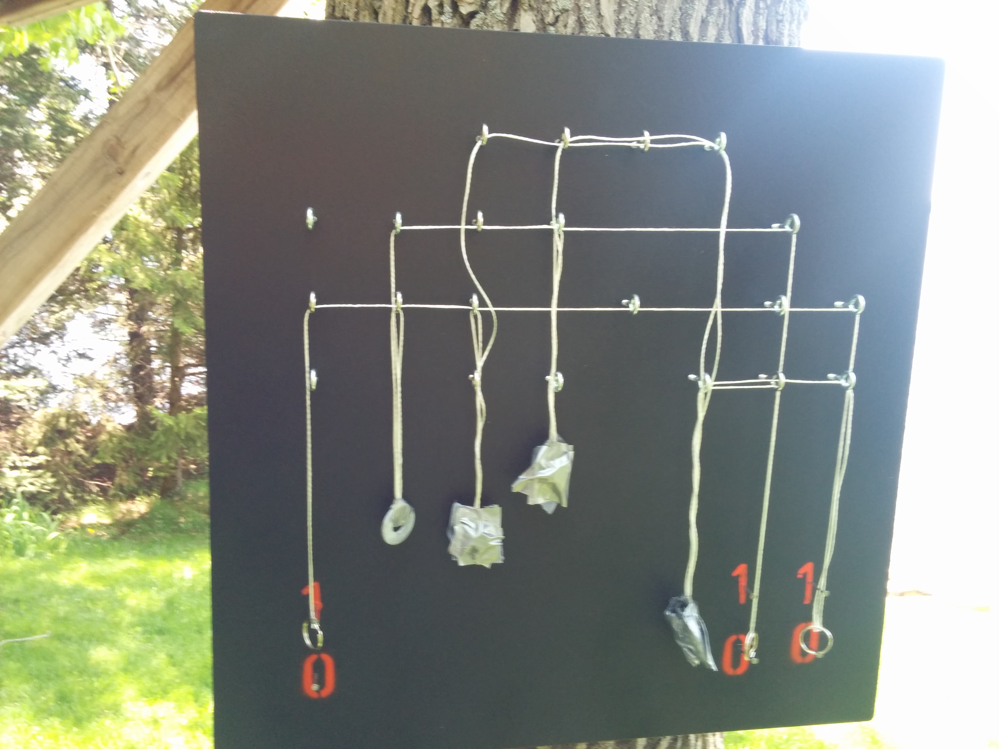 |
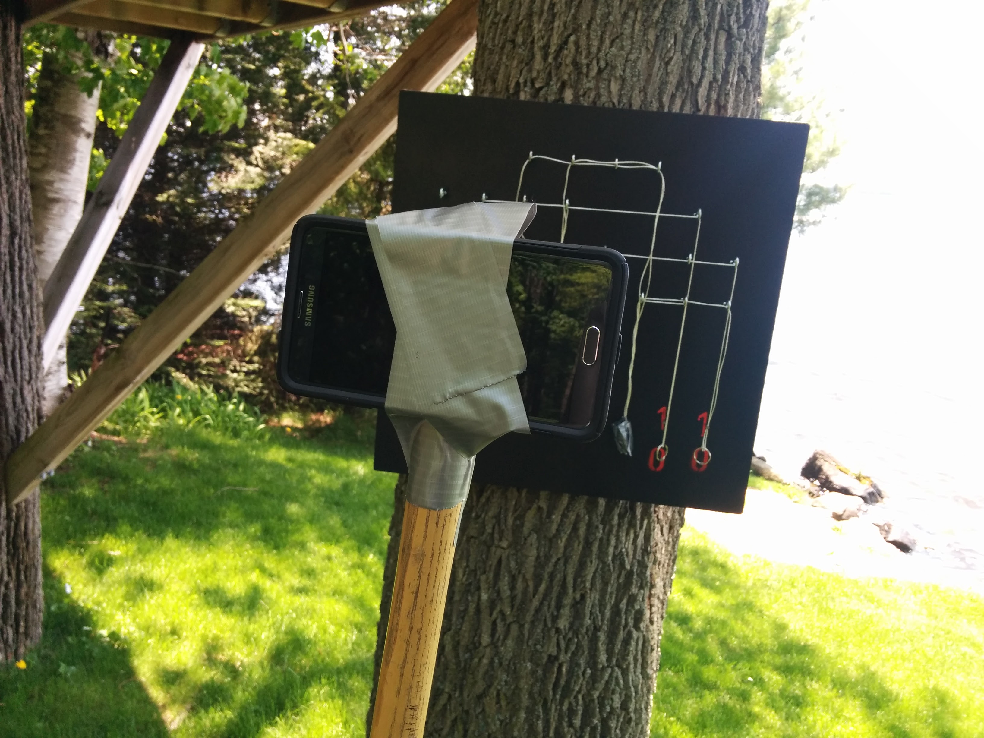
| Picture of the logic gate representation using 7-segment displays | XNOR gate using string and weights |
| Link to YouTube Video: https://www.youtube.com/watch?v=MZ53HkrWRAo | |
Conclusion
Although this project taught me little that I did not already know, I did learn about logic gates in a new, informative way. I believe that this project is useful for teaching someone with little knowledge on electronics about logic gates. Although I was weary of my ISP choice at first, I think that I made a good decision in choosing it. I enjoyed challenging myself to look at logic gates in a different way. I especially enjoyed using and learning about tools that are not often used in a hardware class. The project, when set up properly, is successful in completing its purpose. It was satisfying to see the work and time spent on this project pay off.
Reference
Gorischek, Alex. XNOR. Digital image. Flickr. N.p., 4 May. 2014. Web. 23 May 2016. https://www.flickr.com/photos/10242956@N05/14102324341/in/album-72157644097414107/. Gorischek, Alex. XOR. Digital image. Flickr. N.p., 4 May. 2014. Web. 23 May 2016. https://www.flickr.com/photos/10242956@N05/14102461472/in/album-72157644097414107/.