Automatic Night Light
Purpose
The purpose of this project is to create a night light that automatically turns on two LEDs when in darkness and off when light is detected. The night light must be adjustable to turn on and off with the amount of light in any room with a potentiometer.
| Parts List | |
|---|---|
| 9V Battery | 9V Battery Adapter |
| 9V Power Supply | 5KΩ-200KΩ Photosensitive Resistor |
| 2× Red 5mm LED | 470Ω Resistor |
| 22KΩ Resistor | 100KΩ Potentiometer |
| 3094 NPN Transistor | Small Circuit Board |
| Container (power line Ethernet adapter) | SPDT Switch |
| Black Duct Tape |
Procedure
The Automatic Night Light project began by implementing the circuit diagram found on the RSGC ACES website onto a breadboard. Powering the prototype was a 9V battery. The battery connected to the power rails via a switch. A 10KΩ potentiometer connected to the positive rail and grounded itself through the photo resistor. It was also grounded by a 22KΩ resistor connected to an NPN transistor. The collector leg of the transistor connected to the positive rail and the emitter connected to a 470Ω resistor followed by 2 LEDs in series. The LEDs were then connected to the ground rail. Testing of the circuit ensued to ensure proper operation.
The production of the final project began by selecting a container and measuring it to make certain that the components would fit. The container needed modifications to fit the circuit and power supply. Using a dremel the case was then modified to fit the 9V power supply and circuit board. The resistors and transistor were then soldered to the circuit board. After adequate cooling the 9V power supply and 9V battery connector were then soldered to the switch. The switch connected the power sources to the circuit and prevented over-voltage. Holes for the potentiometer, photo resistor and LEDs were then drilled into the container. The locations chosen for the drill holes allowed proper operation of the photo resistor, easy adjustment of the potentiometer and plenty of light output. The LEDs, potentiometer and photo resistor were then soldered to the circuit board.
The container was finally pieced together and sealed with hot glue. The nuts on the potentiometer and switch were then tightened to be snug but not crack the container. Any excess hot glue was then removed with a knife. The container was then wrapped in black duct tape to provide a stealthier and cleaner look.
Media
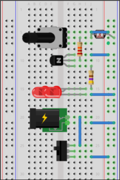 | 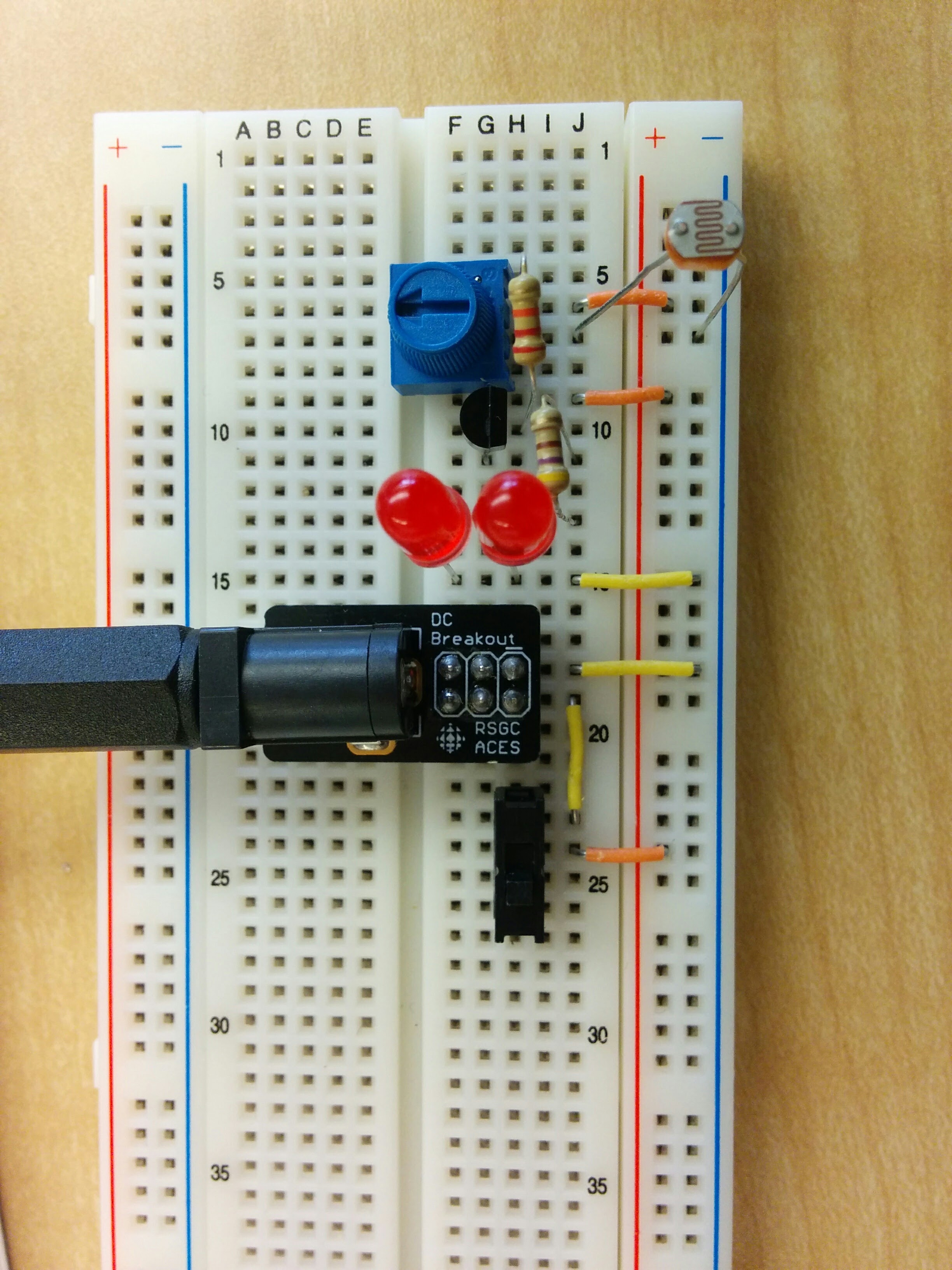 |
| Fritzing Diagram | Finished Breadboard |
|---|---|
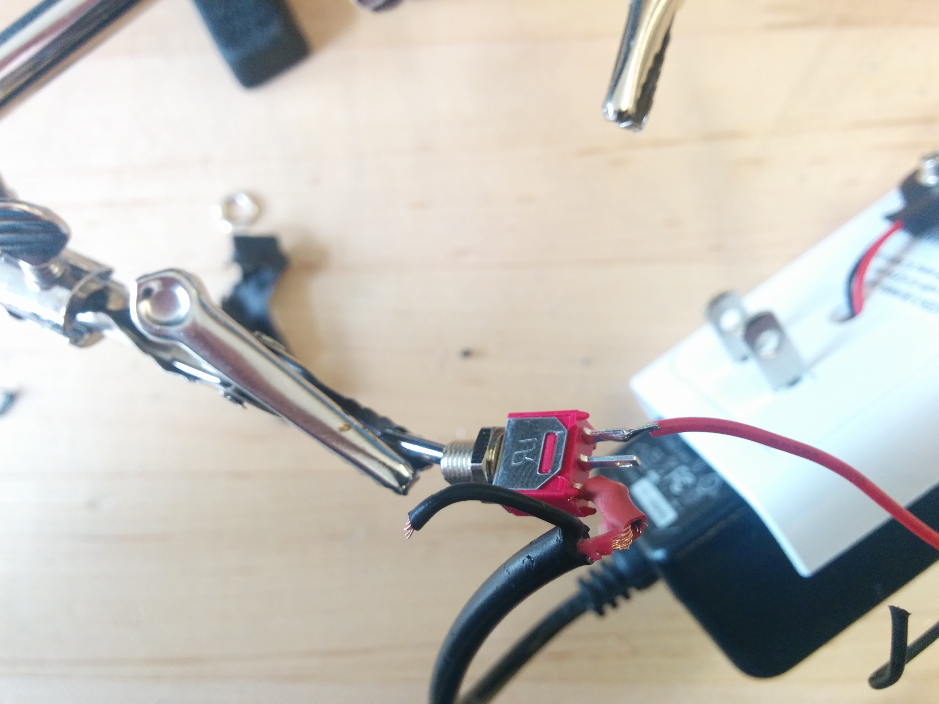 | 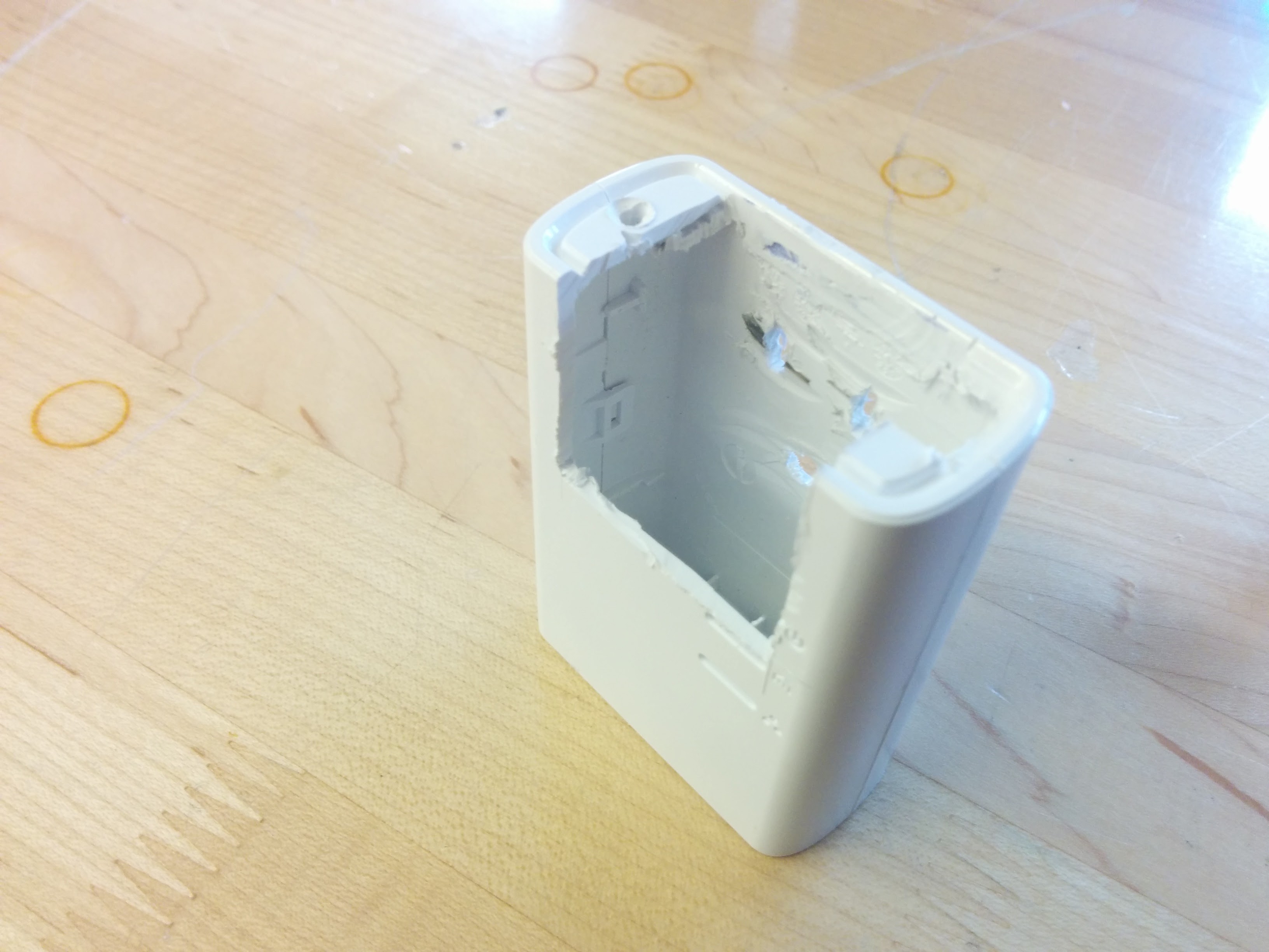 |
| Soldering the switch | Container after cutting with Dremel |
| Link to YouTube Video: https://www.youtube.com/watch?v=51Pw1j0X9qs | |
Conclusion
In conclusion, I would consider this project to be successful in completing its purpose. The night light works as expected and as designed without any issues. I found this project to be both fun and challenging. This project forced me to get creative. I also learned a lot about how transistors and circuits work. The photo resistor taught me how to use an indirect relationship (in this project it was an indirect relationship with light) to perform a desired task. I believe that I the time I put into this project was well spent and helped me reach my desired goal.
Reference
D'Arcy, Chris. "RSGC ACES." RSGC ACES. RSGC, n.d. Web. 09 Apr. 2016. http://darcy.rsgc.on.ca/.